background image

Protocol Variants

18 (32)

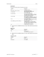
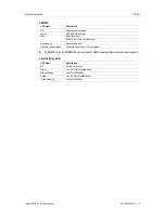
STAT LED

STAT

LED (

1

) reflects status of EtherCAT communication.

LED state

Description

Comments

Off

Init

Interface in INIT state

Green

Operational

Interface in OPERATIONAL state

Green flashing

Pre-operational

Interface in PRE-OPERATIONAL state

Green single flash

Safe-operational

Interface in SAFE-OPERATIONAL state

Flickering

Boot

Interface in BOOT state

Red

If ERR LED

2

also red:

fatal error

Internal error forces interface to passive state

If

STAT

LED (

1

) and

ERR

LED (

2

) are red contact HMS Industrial Networks technical

support.

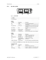
ERR LED

ERR LED

2

indicates EtherCAT communications errors.

LED state

Description

Comments

Off

Not initialized

Interface in SETUP or NW_INIT state

Red blinking

Invalid configuration

State change received from master not possible due
to invalid register of object settings

Red single flash

Unsolicited state change

Slave device application has changed the state
autonomously

Red double flash

Application watchdog
timeout

Sync manager watchdog timeout

Red

Application controller
error

Interface in EXCEPTION state

Flickering

Booting error

E.g. due to firmware download failure

If

STAT

LED (

1

) and

ERR

LED (

2

) are red contact HMS Industrial Networks technical

support.

Link/Activity LED

Link/Aktivity LEDs (

3

) indicate EtherCAT link status and activity.

LED state

Description

Comments

Off

No link

No link, no communication present

Green

Link

Ethernet link established, no communication present

Green flashing

Activity

Ethernet link established, communication present

INpact Slave PCIe User Manual

4.01.0320.20000

1.7

Summary of Contents for IXXAT INpact Slave PCIe

Page 1: ...INpact Slave PCIe Industrial Ethernet PCIexpress Interface USER MANUAL 4 01 0320 20000 1 7 ENGLISH...

Page 2: ...tions codes and standards HMS Industrial Networks will under no circumstances assume liability or responsibility for any problems that may arise as a result from the use of undocumented features timin...

Page 3: ...ry 5 4 Product Description 6 5 Installation 6 5 1 Installing the Software 6 5 2 Installing the Hardware 7 5 3 Connectors 9 6 Configuration 10 6 1 Downloading and Updating the Protocol Specific Firmwar...

Page 4: ...Contents 10 Support Return Hardware 28 10 1 Support 28 10 2 Return Hardware 28 11 Disposal 28 A Regulatory Compliance 29 A 1 EMC Compliance CE 29 A 2 FCC Compliance Statement 29 B Measurements 30 B 1...

Page 5: ...HMS Anybus CompactCom 40 Network Guides HMS INpact Slave Getting Started HMS 1 3 Document History Version Date Description 1 0 March 2016 First release 1 1 April 2016 Added INpact CE Slave PCIe Mini 1...

Page 6: ...This is an external link URL www hms networks com Safety advice is structured as follows Cause of the hazard Consequences of not taking remediate action How to avoid the hazard Safety signs and signa...

Page 7: ...d the product Do not paint the product Do not modify or disassemble the product Service must be carried out by HMS Industrial Networks Do not use modified products Store products in dry and dust free...

Page 8: ...on with very low latency transparent network service channel enables profile integration Drive Motion Semi Other standardized hardware and software interface independent of network continuous product...

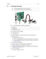
Page 9: ...urer If PCIe Mini or M 2 is used Install the bus coupling unit 2 Connect the interface 4 and the bus coupling unit 2 with the connection cable 3 If the bus coupling unit M12 is used connect the LED co...

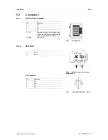
Page 10: ...Function Recommended color Signal name 1 LED U1 Green USR1_LED_GR_EXT 2 Power LED Green NetD100_2 3 LED U1 Red USR1_LED_RD_EXT 4 Ground GND 5 LED NS Network Status Green NW_LED1A_EXT 6 Ground GND 7 LE...

Page 11: ...re signal integ rity pins are tied together and terminated to PE via filter circuit in interface Housing Cable shield 5 3 2 M12 Port Fig 4 M12 connectors on bus cou pling unit M12 1 Port 1 2 Port 2 Fi...

Page 12: ...alled Check FPGA version and interface firmware version in the Windows Device Manager in the tab Hardware Info in the following drop down menus CARD Info FPGA 00 01 03 05 firmware running Version 00 0...

Page 13: ...Powerlink firmware use the Transport Provider or update via the application Fig 6 Configure protocol System conditions 1 Windows computer with HMS firmware manager and ETH protocol files 2 Target syst...

Page 14: ...c LED indications If necessary relabel LED NS and LED MS to conform to specific network certification requirements If the download is interrupted the download is corrupted Use the INpact Recovery Help...

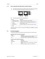
Page 15: ...work status protocol specific 2 LED MS Interface Status Indicates current module and interface status protocol specific 3 LED U1 Indicates state of boot up sequence see Boot Up Sequence p 14 4 LED U2...

Page 16: ...ommunication status protocol specific 6 Port 1 7 Port 2 Depending on the protocol in use a test sequence of LED NS 1 and LED MS 2 is performed during the startup 7 2 Boot Up Sequence In all protocols...

Page 17: ...for Ethernet networks web server with customizable content FTP server e mail client JSON functionality Server Side Include SSI functionality Transparent Socket Interface 8 1 2 Operation LEDs Observe p...

Page 18: ...een In WAIT_PROCESS state Red EXCEPTION error Link Activity LED LED state Description Off No link no activity Green Link 100 Mbit s established Green flashing Activity 100 Mbit s Yellow Link 10 Mbit s...

Page 19: ...ADIs can be accessed from the network as Manufacturer Specific Objects and Device Profile Specific Objects modular device profile enabled up to 1486 bytes of fast cyclic I O in each direction file acc...

Page 20: ...P or NW_INITstate Red blinking Invalid configuration State change received from master not possible due to invalid register of object settings Red single flash Unsolicited state change Slave device ap...

Page 21: ...er with customizable content FTP server e mail client Server Side Include SSI functionality customizable identity information up to 65535 ADIs CIP parameter object expandable CIP object implementation...

Page 22: ...timed out CIP class 1 or 3 LED MS LED state Description Off Application not started Green Controlled by scanner in RUN state Green flashing Not configured or scanner in IDLE state Red Major error EXCE...

Page 23: ...n Profile Specification version 1 2 0 Controlled Node integrated hub 100 Mbit s half duplex operation ring redundancy customizable identity information 1 TPDO and 1 RPDO each can hold 1490 bytes up to...

Page 24: ...rocess data must be ignored Green NMT_CS_OPERATIONAL fully operational asynchronous and synchronous da ta PDO data is sent and received Green fast flashing on 200 ms off 200 ms NMT_CS_STOPPED interfac...

Page 25: ...ostic support complies with PROFINET IO conformance class C up to 1440 bytes I O data in each direction status bytes included SNMP agent FTP server e mail client Server Side Include SSI functionality...

Page 26: ...tion error Expected information differs from real identification LED MS LED state Description Comments Off Not initialized Interface in setup or NW_INITstate Green Operational Interface in OPERATIONAL...

Page 27: ...8 6 2 Operation LEDs Fig 14 LEDs Modbus 1 LED NS 2 LED MS 3 Link Activity LED LED NS LED state Description Off No IP address or EXCEPTION state Green At least one Modbus message received Green flashin...

Page 28: ...ashing red and green Firmware update from file in progress If LED NS 1 and LED MS 2 are red contact HMS Industrial Networks technical support Link Activity LED LED state Description Off No link no act...

Page 29: ...with cable Weight Approx 26 g interface cable bus coupling unit Operating temperature 40 C to 60 C Storage temperature 40 C to 85 C Power supply Via PCIe 3 3 V DC Current consumption Typ 600 mA 3 3 V...

Page 30: ...use support phone contacts on www ixxat com 10 2 Return Hardware Fill in the form for warranty claims and repair on www ixxat com Print out the Product Return Number PRN resp RMA Pack product in a phy...

Page 31: ...1700 Chicago IL 60601 Phone 1 312 829 0601 Any changes or modifications not expressly approved by HMS Industrial Networks could void the user s authority to operate the equipment This equipment has be...

Page 32: ...Appendix B Measurements 30 32 B Measurements B 1 Ethernet Bus Coupling Unit All measurements are in mm INpact Slave PCIe User Manual 4 01 0320 20000 1 7...

Page 33: ...Appendix B Measurements 31 32 B 2 M12 Bus Coupling Unit All measurements are in mm INpact Slave PCIe User Manual 4 01 0320 20000 1 7...

Page 34: ...last page 2018 HMS Industrial Networks AB Box 4126 300 04 Halmstad Sweden info hms se 4 01 0320 20000 1 7 7883 2018 03 16...

Reviews: