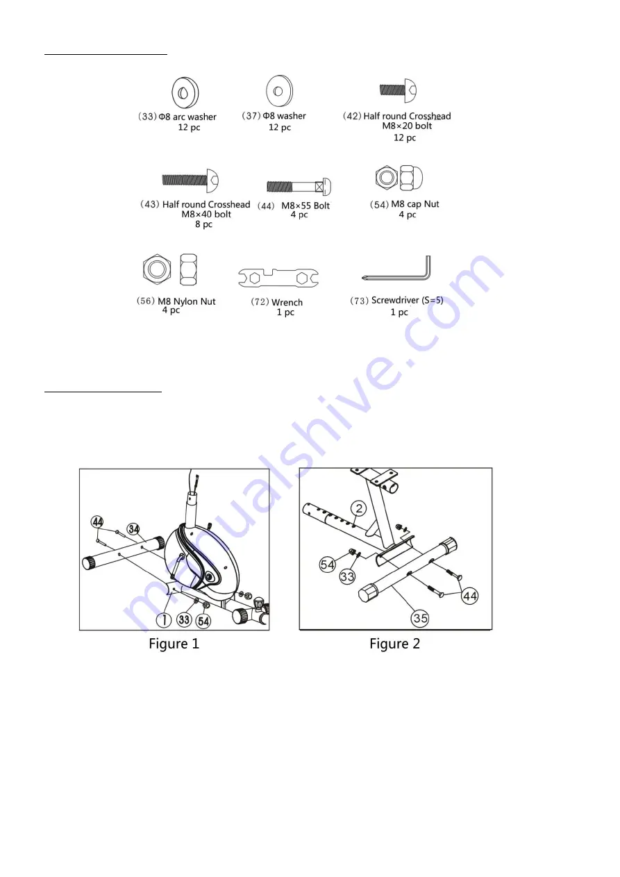
HARDWARE PACKING LIST
ASSEMBLY INSTRUCTION
1) Attach the Front Stabilizer
Attach the Front stabilizer (34) to the Mainframe (1) with two pcs of M8X55 Bolts (44), 2pcs ofΦ8 Arc washer (33), and 2 pcs of
M8 Cap nuts (54). (Refer figure 1)
2) Attach the Rear Stabilizer
Attach the Rear stabilizer (35) to the Seat cushion adjustor (2) with two M8X55 Bolts (44), and 2 pcs of Φ8 Arc washers (33), and
2 pcs of M8 Cap nuts (54). (Refer figure 2)
3) Attach the Front Upright Frame
a.
Pull out the Sensor wire (55) and hand pulse wire 3 (60) through Front upright tube (11).
b.
Connect the tension control (10) with Tension control wire (6); [Noted: First screw the tension control to the end of “-” side,
(Under this circumstance the resistance cable stretch longest.) Put the cable end of the resistance cable into the spring
hook of Tension Control Wire as shown on drawing
A
of figure 3. Pull the Tension Control wire (6) up and force it into the
gap of metal bracket of Tension Control Wire (6) as shown on drawing
B
of figure 3. Connect the resistance with the
Tension Control Wire (6) completed as shown on drawing
C
of figure 3. If the resistance cable can not fit in the metal
bracket, please adjust the nut below the metal bracket.] (See Figure 3 A-C)
c.
Insert the Front upright tube (11) into the tube of Mainframe (1) and secure it with four M8×20 Bolts (42) andΦ8 Arc
washers (33) as shown on drawing
D
of figure 3.
Summary of Contents for R9203
Page 24: ......


