45
Parameters related to SEMI F47 specification support functions are as follows.
Pn424
Torque limitation when main loop voltage drops
Speed
Position
Torque
Setting range
Setting Unit
Factory setting
Effective time
Category
10
~
100
1% *
50
Effective
immediately
Setup
Pn425
Torque limit release time when main loop voltage drops.
Speed
Position
Torque
Setting range
Setting Unit
Factory setting
Effective time
Category
10
~
1000
1 ms
100
Effective
immediately
Setup
Pn509
Transient outage holding time
Speed
Position
Torque
Setting range
Setting Unit
Factory setting
Effective time
Category
20
~
50000
1 ms
20
Effective
immediately
Setup
* Percentage relative to rated torque of motor.
(Note) When using functions meeting SEMI F47 specifications, please set it to 1000 ms
Important
This function is applicable to the instantaneous power failure of voltage and time within the scope specified
in SEMI F47 specification. For the instantaneous power failure of voltage and time beyond this scope,
standby UPS is required.
When the power supply of the main circuit is restored, please use the torque limit set by the upper device
or servo drive to prevent the output torque from being greater than the commanded acceleration torque.
When used for vertical shafts, do not limit the torque below the holding torque.
This function is to limit the torque within the servo drive capability in the power failure state, and is not
applicable to all load conditions or operating conditions. Please be sure to set the parameters while
confirming the action through the actual device.
After setting the holding time of instantaneous power failure, the time from power cut-off to power cut-off of
the motor will become longer. When the motor is powered off immediately, please use the servo
OFF(SV_OFF)
6.4 Setting of Maximum Speed of Motor
The maximum speed of the servo motor is set by the following parameters.
Pn316
Maximum speed of motor
Speed
Position
Torque
Setting range
Setting Unit
Factory setting
Effective time
Category
0
~
65535
1 min
-1
10000
Power restart
Setup
By reducing the maximum speed of the servo motor, the servo drive can realize the following processing.
A.510 (overspeed alarm) occurs when the motor speed exceeds the set value.
Valid when changing parameter settings in the following situations.
In order to protect the machinery, it is necessary to stop the operation of the machinery through an alarm
when the set speed is exceeded.
When the speed needs to be limited so that the motor drives the load above the allowable moment of inertia
6.5 Encoder frequency division pulse output
The encoder frequency division pulse output is a signal that is output to the outside in the form of 2-phase
pulses (phase A and phase B) with a phase difference of 90 degrees after the servo drive internally processes
the signal sent by the encoder. It is used as position feedback in the upper device.
The form of the signal and the output phase is as follows.
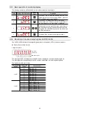
6.5.1 Signal output by encoder frequency division pulse
Type
Signal
name
Connector
pin number
Name
Remarks
Output
PAO+
CN1-19
Encoder
frequency
division
pulse
output
phase A
When the encoder frequency-divided pulse is
output, the number of pulses set by the encoder
frequency-divided pulse number (Pn212) is the
number of pulses that the motor rotates once. The
phase difference between phase A and phase B is
90 degrees.
PAO-
CN1-20
PBO+
CN1-21
Encoder
frequency
division
pulse
output
phase B
PBO-
CN1-22
PCO+
CN1-23
Encoder
frequency
division
pulse
output
phase C
The motor rotates once to output one pulse.
PCO-
CN1-24


