74
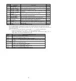
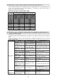
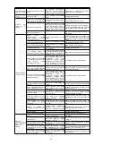
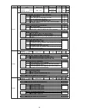
Alarm number:
Alarm name
Reason
Confirmation method
The treatment measures
A.840
:
Encoder data alarm
(Detected on encoder
side
)
Encoder malfunction
-
Connect to the servo drive power supply
again. When an alarm still occurs, replace the
servo motor or encoder.
Incorrect operation of encoder due to
interference, etc
-
Correct
wiring
of
encoder
periphery
(separating encoder cable from servo motor
main loop cable, grounding treatment, etc.).
A.850
:
Encoder overspeed
(detected when
the
control power is turned
on)
(Detected on encoder
side
)
When the control power supply is turned
on, the motor rotates at a speed of 200
min
-1
or more (when rotating the servo
motor)
Confirm the motor speed when the power
supply is turned on through the motor
rotation speed.
Adjust the rotation speed of servo motor to
less than 200min
-1
, and then switch on the
control power supply.
Encoder failure
-
Connect to the servo drive power supply
again. When an alarm still occurs, replace the
servo motor or encoder.
Servo drive failure
-
Connect to the servo drive power supply
again. When an alarm still occurs, replace the
servo drive.
A.b6A
:
MECHATROLINK
Communication
ASIC
fault 1
Servo
drive
MECHATROLINK
communication failure
-
Connect to the servo drive power supply
again. When an alarm still occurs, replace the
servo drive.
A.b6b
:
MECHATROLINK
Communication
ASIC
fault 2
Due to interference, MECHATROLINK
communication caused misoperation.
-
Take the following anti-interference measures.
Correct the connection of communication
cable or FG.
Install ferrite cores on communication cables.
Servo
drive
MECHATROLINK
communication failure
-
Connect to the servo drive power supply
again. When an alarm still occurs, replace the
servo drive.
A.C10
:
Out of control detection
(detected when servo is
ON)
U, V, W phase sequence error of motor
wiring
Confirm the wiring of motor.
Confirm whether there is any problem with the
motor wiring.
Encoder failure
-
Whether there is no problem with the wiring of
the motor, if the alarm still occurs after the
power is switched on again, it may be the fault
of the servo motor or encoder. Replace the
servo motor or encoder.
Servo drive failure
-
Connect to the servo drive power supply
again. When an alarm still occurs, replace the
servo drive.
A.C20
:
Phase error detection
Linear encoder signal level low
Confirm the voltage of the linear encoder
signal
Installation of reading head of fine grating
ruler. Or replace the linear encoder.
The positive counting direction of the
linear encoder does not match the
positive direction of the motor rotor
Confirm the setting of Pn080=n.
X
(motor phase sequence selection) and the
installation direction of linear encoder and
motor rotor.
Change
the
setting
of
Pn080=n.
X
.Reinstall the linear encoder
and motor rotor.
The magnetic pole sensor signal is
disturbed
-
Correct FG wiring. Implement anti-interference
countermeasures for magnetic pole sensor
wiring.
A.C21
:
Magnetic pole sensor
failure
Linear encoder grating scale pitch
(Pn282) setting error
Confirm linear encoder grating pitch
(Pn282).
Confirm the specifications of linear encoder
and set the value correctly.
The magnetic pole sensor is exposed
outside the motor stator
Confirm magnetic pole sensor.
Reinstall the motor rotor or stator.
Incorrect wiring of magnetic pole sensor Confirm the wiring of magnetic pole sensor. Correct the wiring of magnetic pole sensor.
Magnetic pole sensor failure
-
Replace the magnetic pole sensor.
A.C22
:
Phase information is
inconsistent
Servo unit and linear encoder
Phase information is different
-
Perform magnetic pole detection.
A.C50
:
Magnetic pole detection
failed
Parameter setting incorrect
Confirm the specifications of the linear
encoder and the status of the feedback
signal.
The settings of linear encoder grating pitch
(Pn282) and motor phase sequence selection
(Pn080 = n.
X
) may not be consistent
with the state of the device.Set parameters
correctly.
The grating scale signal is disturbed
Confirm that the serial conversion unit, FG
of servo motor and FG of servo unit are
connected, and FG of servo unit is
connected with FG of power supply. In
addition, it is confirmed that the cable of the
linear encoder is indeed shielded. Confirm
whether the detection command is
repeatedly output in the same direction for
many times.
Take appropriate anti-interference measures
for cables used for linear encoders.
The motor rotor is subjected to external
force
-
Even if the detection command is 0 and the
speed feedback is not 0 when external force
such as cable tension is applied to the motor
rotor, and it cannot be detected smoothly.
Reduce the external force so that the speed
feedback is 0. Increase the magnetic pole
detection speed loop gain (Pn481) when the
external force cannot be reduced.
Linear encoders have low resolution
Confirm whether the pitch of linear encoder
grating ruler is within 100 m.
When the pitch of linear encoder grating scale
is more than 100m, the servo unit cannot
detect the correct speed feedback. Use high
precision linear encoder grating scale pitch
(within 40m is recommended). Or increase the
magnetic pole detection command speed
(Pn485). However, the motor operation range
when magnetic poles are detected becomes
larger.
A.C51
:
Over-travel
detection
when magnetic pole is
detected
Over-travel signal is detected when
magnetic pole is detected
Confirm the overtravel position.
Connect the over-travel signal. Magnetic pole
detection is carried out at the position where
the over-travel signal cannot be detected.
A.C52
:
Magnetic pole detection
is not complete
Servo ON in the following states
• When magnetic pole detection is not
completed
• When/p-det is not entered
-
Input /P-DET signal.
A.C53
:
The
magnetic
pole
detection is beyond the
active range
The detection moving distance exceeds
the magnetic pole detection moving
range.
(
Pn48E
)
-
Expand the range of magnetic pole detection
activities (Pn48E). Or increase the pole
detection speed loop gain (Pn481).
A.C54
:
Magnetic pole detection
failed 2
Under external force
-
Increase the value of the magnetic pole
detection
confirmation
thrust
command
(Pn495). Increase the allowable range of
magnetic pole detection error (Pn498).
However, once the error tolerance range is
expanded, the motor temperature will rise.

