17
00.09
Digital frequency
control
LED bits: power-down storage
0: store
1: do not store
LED ten-bit: stop hold
0: hold
1: do not keep
LED 100-digit: UP/DOWN negative frequency adjustment
0: invalid
1: valid
LED thousand bits: frequency superposition selection of PID and PLC
0: invalid
1
:
00.03+PID
2
:
00.03+PLC
0000
~
2111
0000
○
00.10
Acceleration time
Time required for inverter to accelerate from 0Hz to maximum output
frequency
0.1
~
999.9S
Default:
0.4
~
4.0KW - 7.5S
5.5
~
7.5KW - 15.0S
Model
setting
○
00.11
Deceleration time
Time required for inverter to decelerate from maximum output frequency
to 0Hz
00.12
Running direction
setting
0: forward rotation 1: reverse rotation 2: reverse rotation prohibited
0
~
2
0
○
00.13
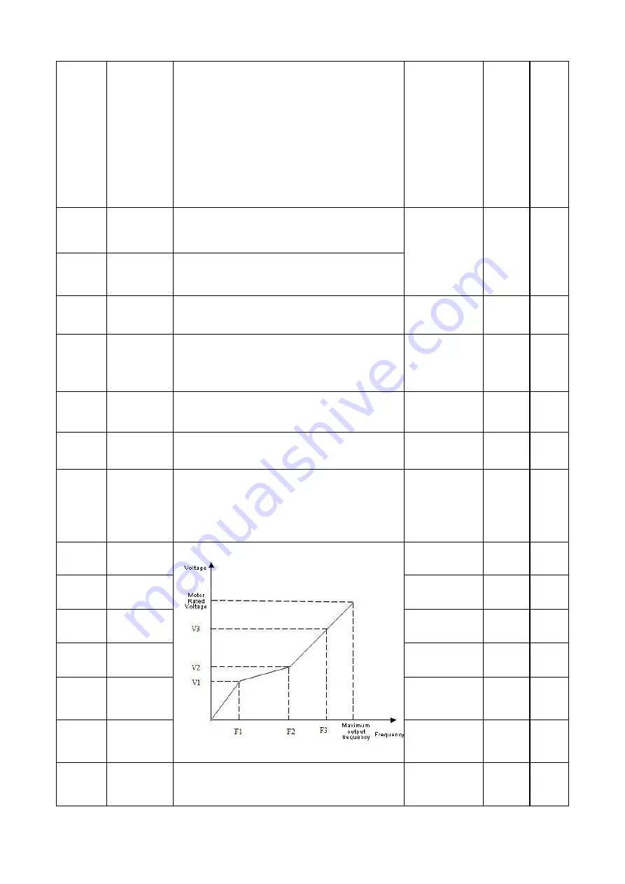
V/F curve setting
0: linear curve
1: Square curve
2: Multi-point VF curve
0
~
2
0
×
00.14
Torque boost
Manual torque lift.
This setting is a percentage relative to the rated voltage of the motor.
0.0
~
30.0%
Model
setting
○
00.15
Torque boost
cutoff frequency
This setting is the lifting cut-off frequency point when manual torque is
lifted.
0.0
~
50.0Hz
15.0Hz
×
00.16
Carrier frequency
setting
When silent operation is needed, the carrier frequency can be
appropriately increased to meet the requirements, but increasing the
carrier frequency will increase the calorific value of the inverter.
2.0
~
16.0KHz
0.4
~
3.0KW 4.0KHz
4.0
~
5.5KW 3.0KHz
Model
setting
×
00.17
V/F frequency F1
0.1
~
Frequency
value 02
12.5Hz
×
00.18
V/F Voltage V1
0.0
~
voltage value
V2
25.0
%
×
00.19
V/F frequency F2
Frequency value
01
~
frequency
value 03
25.0Hz
×
00.20
V/F Voltage V2
Voltage value v1
~
voltage value V3
50.0%
×
00.21
V/F frequency F3
Frequency value
02
~
rated
frequency of motor
【
04.03
】
37.5Hz
×
00.22
V/F Voltage V3
Voltage value v2
~
100.0% * uoute (rated
voltage of motor
[04.00])
75.0%
×
00.23
User password
Set any non-zero number, and wait for 3 minutes or RESTART before it
takes effect.
0
~
9999
0
○


