2
I. Technical indicators and specifications of products
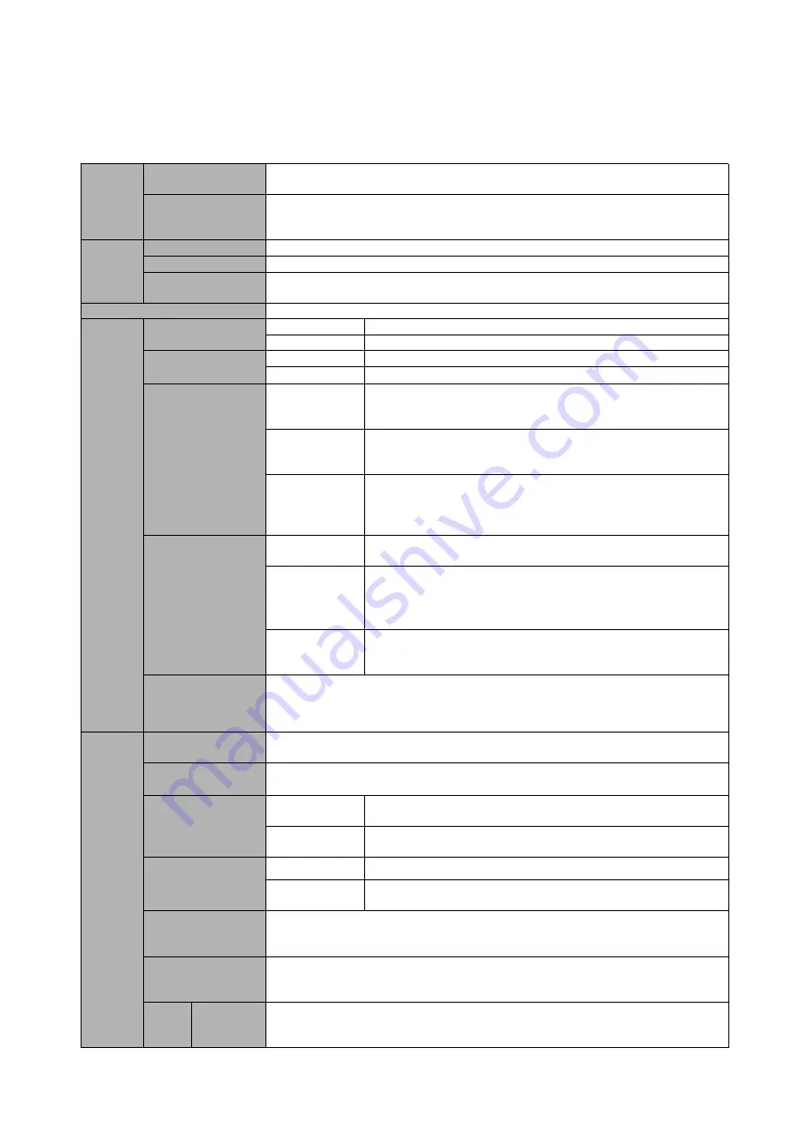
Input
Rated voltage ,
Frequency
Three-phase (G3/G4 series) 380V-480V, 50/60HZ
Single&Three-phase (G1/G2 series) 220 V: 50/60 Hz
Allowable range of
voltage variation
Three-phase (G3 series) : AC 380~440 (-15%~+10%)
Three-phase (G4 series) : AC 460~480 (-15%~+10%)
Single&Three-phase (G1/G2 series) : AC220V±15%
Output
Voltage
G1/G2 series; 0
~
220V, G3 series; 0
~
440 V, G4 series; 0
~
480 V
Frequency
0
~
999.9HZ
Overload capacity
110% long-term
;
150% 1 minute
;
180% 5 seconds
Control mode
V/F control, Vector control
Control
characteri
stic
Frequency setting
resolution
Analog input
0.1% of the maximum output frequency
Digital settings
0.1HZ
Frequency accuracy
Analog input
Within 0.2% of the maximum output frequency
Digital input
Within 0.01% of the set output frequency
V/F control
V/F curve (voltage
frequency
characteristic)
Three ways: the first is linear torque characteristic curve, the second is square
torque characteristic curve, and the third is user-set V/F curve
Torque boost
Manual setting: 0.0
~
30.0% of rated output
Automatic lifting: automatically determine the boost torque according to the
output current and motor parameters
Automatic current
and voltage
limiting
Whether in acceleration, deceleration or stable operation, the motor stator
current and voltage can be automatically detected, which can be suppressed
within the allowable range according to the unique algorithm to minimize the
possibility of system fault tripping
Sensorless vector
control
voltage frequency
characteristic
Automatically adjust output voltage-frequency ratio according to motor
parameters and unique algorithm
Torque
characteristic
Starting torque:
100% rated torque at 5.0Hz (VF control)
150% rated torque at 0.5Hz (Vector control)
Current and
voltage
suppression
Full-range current closed-loop control, completely avoiding current impact,
with perfect overcurrent and overvoltage suppression function
Undervoltage
suppression during
operation
Especially for users with low grid voltage and frequent fluctuation of grid voltage, the system can
maintain the longest possible operation time according to the unique algorithm and residual energy
allocation strategy even in the range below the allowable voltage
Typical
function
Multi-stage speed
operation
7-stage programmable multi-stage speed control and multiple operation modes are optional.
PID control
RS485 communication
Built-in PID controller (preset frequency). Standard configuration RS485 communication function,
multiple communication protocols can be selected, with linkage synchronous control function
Frequency setting
Analog input
DC voltage 0
~
10 V, DC current 0
~
20 mA (upper and lower limits are
optional)
Digital input
Operation panel setting, RS485 interface setting, UP/DW terminal setting, and
various combination settings with analog input can also be made.
Output signal
Digital output
1 OC output and 1 relay output (TA,TC), with up to 17 functions
Analog output
1 AO, the output range can be flexibly set between 0
~
20mA or 0
~
10V,
which can realize the output such as set frequency and output frequency.etc
Automatic voltage
stabilizing operation
According to the needs, three modes can be selected: dynamic voltage stabilization, static voltage
stabilization and non-voltage stabilization, so as to obtain the most stable operation effect
Acceleration /
deceleration time
setting
0.1S
~
999.9min can be set continuously
Brake
Energy
consumption
braking
Energy consumption braking starting voltage, return difference voltage and energy consumption
braking rate can be continuously adjusted


