32
The initial value of the frequency setting is 00.08, which can be adjusted with the operation panel keys
or digital encoder. The modified frequency value
will be stored in 00.08 after power failure (if you want this frequency not to be stored, you can set 00.09 bits to 1 to achieve.
2: Digital setting 2, UP/DOWN terminal adjustment
The initial value of the frequency setting is 00.9, and the operating frequency is changed by the on/off of the multi-function terminal defined externally as the UP/DOWN
function (see the function number of the frequency increment and decrement item of the DI terminal in group 02 for details), when the UP terminal and the GND
terminal are closed , The frequency rises; when the DOWN terminal is closed with the GND terminal, the frequency drops; when the UP/DOWN terminal is closed or
disconnected with the GND terminal at the same time, the frequency remains unchanged. If you set the frequency to be stored when power off, the modified frequency
value will be stored in 00.9 after power off. The rate at which the UP/DOWN terminal modifies the operating frequency can be set by function code 02.27.
3: AI analog setting (0
~
10V/20mA)
The frequency setting is determined by the AI terminal analog voltage/current, the input range:
For DC 0
~
10V/20mA related settings, see the definition of function 02.00
~
02.03.
4: Combination given
When the combination is given, the combination setting mode is selected in 01.15.
5: reserved
6: Communication settings
Change the set frequency through the serial port frequency setting command. For details, see Group 06 communication parameters.
7: Reserved
00.04
Maximum output frequency
MAX
{
50.0,
【
00.05
】}~
999.9Hz
50.00
00.05
Upper limit frequency
MAX{0.1Hz
,【
00.06
】
}
~【
00.04
】
50.00
00.06
Lower limit frequency
0.0Hz
~【
00.05
】
0.00
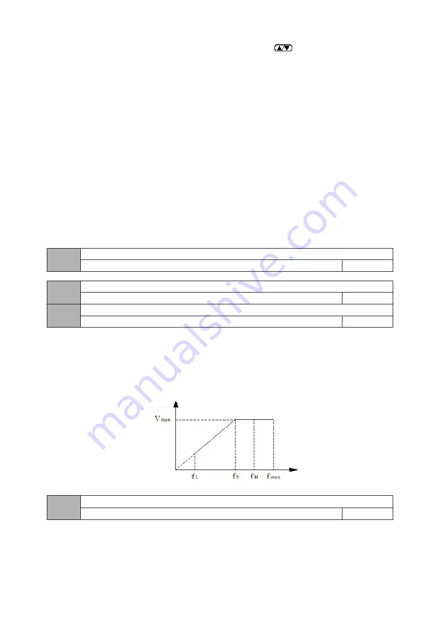
The maximum output frequency is the highest frequency that the inverter allows to output, and is the basis for the acceleration and deceleration time setting, as
shown in the following figure, fmax;
The basic operating frequency is the minimum frequency when the inverter outputs the highest voltage, generally the rated frequency of the motor, as shown in the
following figure fb; the maximum output voltage Vmax is the corresponding output voltage when the inverter outputs the basic operating frequency, generally the motor
rated voltage; Vmax as shown in the figure below; fH and fL are respectively defined as the upper limit frequency and the lower limit frequency, as shown in Fig. 00-1:
Fig. 00-1 Schematic diagram of voltage and frequency
00.07
Action when the set frequency is lower than the lower limit frequency
0
~
2
0
0: Zero speed operation
When the set frequency is lower than the lower limit frequency set value (00.06), the inverter runs at zero speed.
1: Run at the lower frequency limit


