52
03.11
Awakening threshold coefficient
0.0
~
150.0%
90.0
03.12
Sleep delay time
0.0
~
999.9s
1.0
03.13
Wake delay time
0.0
~
999.9s
1.0
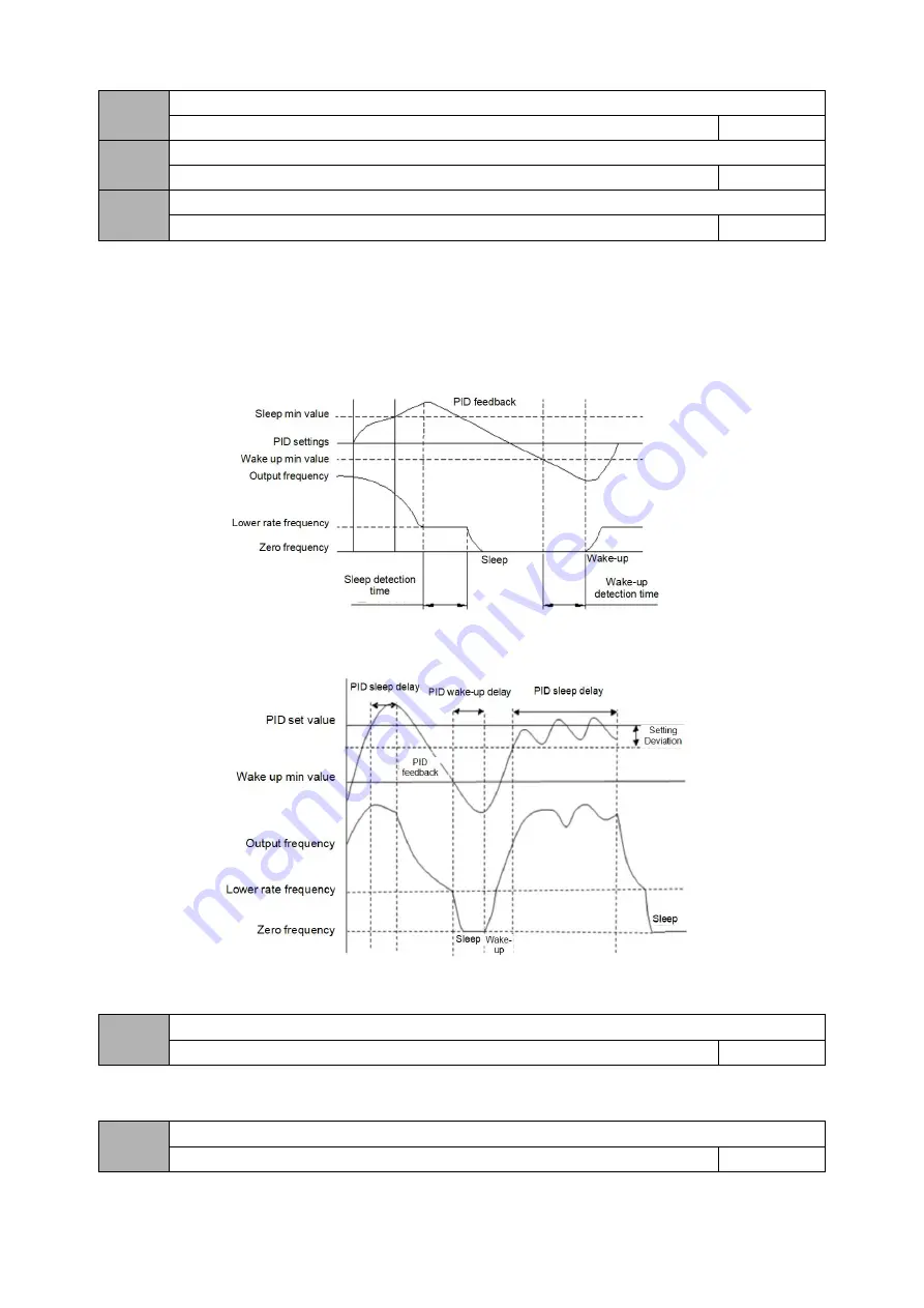
03.10 defines the feedback limit when the inverter enters the sleep state from the working state. If the actual feedback value is greater than the set value, and the
frequency of the inverter output reaches the lower limit frequency, the inverter will enter the sleep state (that is, running at zero speed) after the delay waiting time
defined in 03.12.
03.11 defines the feedback limit of the inverter from the sleep state to the working state. When the PID polarity is selected as the positive characteristic, if the actual
feedback value is less than the set value (or when the PID polarity is selected as the negative characteristic, if the actual feedback value is greater than the set value),
the inverter passes the defined value of 03.13 After delaying the waiting time, it leaves the sleep state and starts to work.
Figure 03-3 Schematic diagram of the first normal sleep mode
Figure 03-4 Schematic diagram of the second disturbed sleep mode
03.14
Deviation between feedback and set pressure when entering sleep
0.0
~
999.9s
1.0
This function parameter is only valid for disturbance sleep mode
03.15
Delay time of burst detection
0.0
~
130.0s
0.0


