background image

HOAC AUSTRIA 

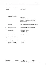
1.5.  DIMENSIONS 

OVERALL DIMENSIONS 

Span without ACL 

Span with ACL 

Length 

Width 

WINGS 

Airfoil 

Wing area 

Mean aerodynamic chord 

(MAC) 

Aspect Ratio 

Dihedral 

Sweep of Leading Edge 

AILERON 

Area 

FLAPS 

Area 

DV 20 Flight Manual 

1 0.78 m (35 ft 4.3 in) 

1 0.84 m (35 ft 6.7 in) 

7.28 m (23 ft  1 0.6 in) 

1 .76 m (5 ft  9.3 in) 

Wortmann FX 63-1 37/20 HOAC 

1 1 .6 m2 (124.8 sq. ft.) 

1 .09 m (3 ft 6.9 in) 
1 0.0 

+4' 

+1 ' 

0.658 m2 (7.08 sq. ft.) 

1 .236 m2 (13.30 sq.ft.) 

HORIZONTAL STABILIZER 

Area 

Elevator Area 

Angle of incidence 

VERTICAL STABILIZER 

Area 

Rudder Area 

LANDING GEAR 

Track 
Wheel base 

Nose wheel 

Main wheel 

Revision No. 

1 .692 m2 (18.21  sq.ft.) 

0.441  m2 (4.75 sq.ft.) 

_2' 

1 .1 34 m2 (12.21  sq.ft.) 

0.426 m2 (4.59 sq.ft.) 

1 .90 m (6 ft 2.8 in) 

1 .75 m (5 ft 8.9 in) 

300*1 00/4.00-4 

380*150/1 5*6.00-5 

Reference 

Date 

October 20, 1 993 

Page 

1  - 4 

General 

Summary of Contents for DV 20 KATANA 1993

Page 1: ...r 20 1993 4 01 02 This manual is part of the airplane DV 20 Katana and must be carried on board at all times Scope and revision status can be found in the List of Effective Pages and in the Record of Revisions TO P d M BAZ pW 0 of E l l ti I P7 Signature tl J LF Authority Stamp Date of approval This airplane is to be operated in compliance with the information and limitations contained herein Page...

Page 2: ...TANA airplane We ask that you carefully read this Flight Manual and to pay special attention to the recommendations given A careful study of the manual will reward you with many hours of trouble free flight operation of your KATANA airplane Revision No All rights reserved Reproduction of this manual or any portion thereof by any means without the express written permission of HOAC Austria is prohi...

Page 3: ...MITATIONS 2 EMERGENCY PROCEDURES 3 NORMAL OPERATING PROCEDURES 4 PERFORMANCE 5 MASS WEIGHT AND BALANCE I EQUIPMENT LIST 6 DESCRIPTION OF THE AIRPLANE AND ITS SYSTEMS 7 HANDLING PREVENTIVE AND CORRECTIVE MAINTENANCE 8 SUPPLEMENTS 9 Revision No Reference Date October 20 1 993 Page 0 3 ...

Page 4: ... 5 Oct 20 1993 3 6 Oct 20 1993 Reference Date Page ACG appr ACG appr ACG appr ACG appr ACG appr ACG appr ACG appr ACG appr ACG appr ACG appr ACG appr ACG appr ACG appr ACG appr ACG appr ACG appr ACG appr ACG appr ACG appr ACG appr ACG appr ACG appr ACG appr ACG appr ACG appr ACG appr ACG appr ACG appr ACG appr ACG appr ACG appr MSB20 39 November 12 2001 3 7 3 8 3 9 3 10 3 11 3 12 3 13 3 14 3 15 3 ...

Page 5: ...ec 30 1994 Dec 30 1994 9 Oct 20 1993 Dec 30 1994 Oct 20 1993 Oct 20 1993 Dec 30 1994 Oct 20 1993 Oct 20 1993 Oct 20 1993 Dec 30 1994 Dec 30 1994 Dec 30 1994 Dec 30 1994 Dec 30 1994 Oct 20 1993 Oct 20 1993 Oct 20 1993 Oct 20 1993 Oct 20 1993 Oct 20 1993 Oct 20 1993 Nov 12 2001 Oct 20 1993 Dec 30 1994 Oct 20 1993 Dec 30 1994 Oct 20 1993 Oct 20 1993 Dec 30 1994 Oct 20 1993 Reference Date MSB20 39 Nov...

Page 6: ...r of the page The airplane may only be operated if the Flight Manual is up to date Rev Chap No ter 0 1 2 3 1 4 5 6 7 0 2 8 0 3 7 Revision No 3 Pages 0 4 thru 0 6 1 6 2 4 2 9 3 2 4 2 4 8 4 11 4 12 4 14 5 4 5 8 5 9 5 12 6 2 6 4 6 5 6 7 6 10 6 14 thru 6 18 7 10 7 12 7 15 0 4 thru 0 6 8 2 0 4 thru 0 6 7 8 Date of Approval Date of Amendment Remarks Approval by Authoritv approved by Dec 3D 1994 lng Jose...

Page 7: ...AC AUSTRIA Rev No Chapter Revision No DV 20 Flight Manual Pages Date of Approval Date of Amendment Remarks Approval by Reference Date October 20 1993 Authority Date of Issue Page 0 7 Signature I Initials ...

Page 8: ...ctors with information for the safe and efficient operation of this airplane This Manual includes the material required to be furnished to the pilot by JAR VLA It also contains supplemental data supplied by the airplane manufacturer which can be useful to the pilot The Flight Manual conforms to the actual version of the customer s airplane Any optional equipment installed on request of the custome...

Page 9: ...ith ICAO annex 16 chapter 10 1 3 WARNINGS CAUTIONS AND NOTES The following definitions apply to warnings cautions and notes used in the Flight Manual Revision No WARNING means that the non observation of the corresponding procedure leads to an immediate or important degradation ofthe flight safety CAUTION means that the non observation of the corresponding procedure leads to a minor or to a more o...

Page 10: ...USTRIA DV 20 Flight Manual 1 4 THREE VIEW DRAWING OF AIRPLANE I II II I I II II I Revision No 5 ft 8 9 in I iii t 23 ft 10 6 in 3 2 in 6 ft 2 8 in Reference 35 ft 4 3 in Date October 20 1993 Page 1 3 General ...

Page 11: ...6 m 5 ft 9 3 in Wortmann FX 63 137 20 HOAC 1 1 6 m2 124 8 sq ft 1 09 m 3 ft 6 9 in 10 0 4 1 0 658 m2 7 08 sq ft 1 236 m2 13 30 sq ft HORIZONTAL STABILIZER Area Elevator Area Angle of incidence VERTICAL STABILIZER Area Rudder Area LANDING GEAR Track Wheel base Nose wheel Main wheel Revision No 1 692 m2 18 21 sq ft 0 441 m2 4 75 sq ft _2 1 134 m2 12 21 sq ft 0 426 m2 4 59 sq ft 1 90 m 6 ft 2 8 in 1 ...

Page 12: ...ler manufactured by HOFFMANN Constant speed hydraulic pitch control model HO V72F S170DW or two bladed variable pitch propeller manufactured by HOFFMANN Constant speed hydraulic pitch control model HO V352F 1 70FQ RANGE OF PITCH ANGLE DIAMETER 1 8 FUEL Approved fuel grades TOTAL CAPACITY USABLE CAPACITY 10 _35 1 70 m 5 ft 6 9 in a AVGAS 100LL b MOGAS in accordance with BAZ Regulation ZI 6412 1 1 1...

Page 13: ...tem The viscosity should be selected according to the various climatic conditions using the following table Avoid using single grade oils Oil Capacity Revision No 1 tropical arctic single grade oils multi gra de oils CAUTION Do not use aviation lubricant Minimum 2 0 liters 2 1 US qt Maximum 3 0 liters 3 2 US qt Reference Dale December 30 1 994 Page 1 6 ...

Page 14: ...olant Capacity Minimum Maximum 2 4 liters 2 5 US qt 2 5 liters 2 6 US qt Reservoir Capacity Minimum Maximum Revision No 0 1 liters 0 11 US qt 0 2 liters 0 21 US qt NOTE The level in the reservoir can be checked using the coolant dipstick Excessive overfilling of the reservoir can result in overflow during operation In the event of a completely empty reservoir the coolant level in the dispatcher ve...

Page 15: ... weight in baggage compartment Maximum useful load including fuel WING LOADING 730 kg 1609 Ibs 730 kg 1609 Ibs See Chapter 6 20 kg 44 Ibs See Chapter 6 At maximum take off mass weight 62 80 kg m2 3 92 Ibs sq ft Performance load at max take off mass weight 12 24 kg kW 20 1 Ibs hp Revision No Reference Date October 20 1993 Page 1 8 General ...

Page 16: ...ound Speed Speed ofthe airplane relative to the ground TAS True airspeed Speed of the airplane relative to air TAS is CAS corrected for altitude and temperature errors VA Maneuvering speed Maximum speed at which the airplane is not overstressed at full deflection of control surfaces VFE Maximum speed with flaps extended VNE Speed which must never be exceeded in any operation VNO Maximum structural...

Page 17: ...ature gradient up to the altitude at which the temperature reaches 55 5 C 67 9 OF is 0 0065 C m 0 0036 FIft and 0 C m 0 F ft above OAT Outside air temperature Indicated Pressure Altitude Altitude reading with altimeter set to 1013 25 mbar 29 92 inHg air pressure Pressure Altitude Altitude measured at standard pressure at MSL 1013 25 mbar 129 92 inHg using a barometric altimeter Pressure altitude i...

Page 18: ...Power Maximum permissible continuous engine output power during flight d Flight Performance and Flight Planning Demonstrated crosswind component The max speed of the crosswind component at which the maneuverability of the airplane during take off and landing has been demonstrated during type certification test flights Service ceiling The altitude at which the maximum rate of climb is 0 5 m s 100 f...

Page 19: ...erence datum Lever Arm The horizontal distance from the reference datum to the center of gravity of a component Moment The mass weight of a component multiplied by its lever arm Center of Gravity Point of equilibrium forthe airplane mass Center of Gravity Arm CG position Distance from the reference datum to the CG It is determined by dividing the total moment sum of the individual moments by the t...

Page 20: ...pecifications Empty Mass Weight Mass Weight of the airplane including unusable fuel all operating fluids and maximum oil amount Useful Load The difference between take off mass weight and empty mass weight Maximum take off mass weight Maximum mass weight permissible for take off f Equipment ACL Anti Collision Light Revision No Reference Date October 20 1993 Page 1 13 ...

Page 21: ... 12 CONVERSION FACTORS LENGTH OR ALTITUDE 1 ft 1 in SPEED 1 kts 1 mph PRESSURE 1 hPa 1 in Hg 1 psi Revision No 0 3048 m 25 4 mm 1 852 km h 1 609 km h 100 N m2 1 mbar 33 865 hPa 68 97 mbar Reference Date October 20 1993 Page 1 14 General ...

Page 22: ...EW 2 9 2 13 KINDS OF OPERATION 2 9 2 14 FUEL 2 9 2 15 LIMITATION PLACARDS 2 10 2 1S DEMONSTRATED CROSSWIND COMPONENT 2 10 2 1 INTRODUCTION Chapter 2 of this Flight Manual comprises the operating limitations instrument markings airspeed indicator markings and the limitation placards which are necessary for the safe operation of the airplane its engine and standard systems and equipment The operatin...

Page 23: ...5 Never exceed speed Revision No Reference km h Remarks 193 Do not make full or abrupt control movement above this speed because undercertain conditions the airplane may be overstressed by full control movement 150 Do not exceed this speed with flaps extended 217 Do not exceed this speed except in smooth air and then only with caution 298 Do not exceed this speed in any operation Date October 20 1...

Page 24: ...evision No lAS kts mph km h Explanation 38 81 44 93 70 150 Operating range with extended flaps 43 117 49 135 80 217 Normal Operating Range 117 161 135 185 217 298 Maneuvers must be conducted with caution and only in smooth air 161 185 298 Maximum permissible speed for all operating modes Reference Date October 20 1993 Page 2 3 ...

Page 25: ...within this manual contrary to the engine manual are propeller speeds c Engine Operating Limitations Max TIO Power 5 min Max Permissible TIO RPM Max Continuous Power Max Permissible Continuous RPM Idle Speed d Oil Pressure Minimum Maximum Max in case of Cold start short term e Fuel Pressure Minimum Maximum f Oil Temperature Minimum Maximum Revision No 1 Reference 59 6 kW 180 hp 2550 RPM 58 kW178 h...

Page 26: ...imum 95 octane leaded or unleaded i Oil Grades Name Brand Automotive Oil also see Page 1 6 j Propeller Manufacturer Hoffmann Propeller RosenheimlGermany k Propeller Type HO V72F S 1 70 DW or HO V352F 1 70FQ I Propeller Diameter 1 70 m 5 ft 6 9 in m Propeller Pitch at 0 75 R 10 _35 n Propeller Speed Limitations max TIO RPM max 5 min 2550 RPM Max Continuous RPM 2420 RPM Revision No Reference Date Oc...

Page 27: ... 73 psi 73 102 psi Fuel Quantity Indicator Manifold Pressure Indicator 2 6 MISCELLANEOUS INSTRUMENT MARKINGS None 2 7 MASS WEIGHT 730 kg 1609 Ibs 730 kg 1609 Ibs Red Line Upper Limit 2550 RPM 140 C 284 OF 150 C 302 F 7 bar 102 psi Maximum permissible take off mass weight Maximum permissible landing mass weight Maximum permissible mass weight in the baggage compartment 20 kg 44 Ibs only permissible...

Page 28: ...e wing at the root rib This plane is vertical when the fuselage is horizontal Procedures for horizontal alignment as well as particulars with regard to the empty mass center of gravity refer to Chapter 6 Most forward CG Most rearward CG 250 mm 9 84 in aft of RD 390 mm 15 35 in aft of RD WARNING Exceeding the center of gravity limitations reduces the maneuverability and stability of the airplane Th...

Page 29: ...OTE Limitations Aerobatics as well as flight maneuvers with bank angles of more than 60 are prohibited 2 10 MANEUVERING LOAD FACTORS Table of structural maximum permissible load factors Positive NeQative Revision No at VA at VNE with fully extended flaps 4 4 4 4 2 0 2 2 2 2 0 WARNING Any exceeding of the maximum load factors will result in overstressing of the airplane Simultaneous full deflection...

Page 30: ...light and Navigation Instruments Airspeed Indicator Altimeter Magnetic Compass Minimum Equipment Powerplant Instruments Fuel Quantity indicator Oil Pressure indicator Oil Temperature indicator Manifold Pressure indicator Cylinder Head Temperature indicator Tachometer Fuel Pressure warning light Low Voltage caution light Generator warning light 2 14 FUEL Fuel Capacity Total fuel quantity Usable Fue...

Page 31: ...ay VFR only in non icing conditions All aerobatic maneuvers including intentional spinning are prohibited See Flight Manual for other limitations No smoking b In the baggage compartment Baggage max 20 kg 44 Ibs only with baggage harness NOTE For further placards refer to the Maintenance Manual Doc No 4 02 02 2 16 DEMONSTRATED CROSSWIND COMPONENT The maximum demonstrated crosswind component is 15 k...

Page 32: ...ary Landing 3 3 3 Fire a Engine Fire During Start On The Ground b Engine Fire During Flight c Electrical Fire Including Smoke During Flight d Electrical Fire Including Smoke On The Ground e Cabin Fire During Flight 3 3 4 Icing a Unintentional Flight Into ICing Area 3 3 5 Recovery From Unintentional Spin 3 3 6 Landing With Defective Tire On Main Landing Gear 3 3 7 Landing With Defective Wheel Brake...

Page 33: ...problems Since it is impossible to present in the Flight Manual all emergency situations which may occur knowledge of the airplane and experience of the pilot are essential in rectifying such problems 3 2 AIRSPEEDS DURING EMERGENCY PROCEDURES Ennine failure after take off with flans in T O nosition Maneuverino Sneed Airspeed for best glide ratio 730 ko 1609 Ibs IFlans in T O Position for all flinh...

Page 34: ...rspeed VIAS 59 kts I 68 mph 1110 km h 2 3 4 5 6 7 8 Throttle FULL Carburetor Heat OFF Choke OFF Fuel Shut off Valve OPEN Ignition Switch BOTH Electric Fuel Pump ON Propeller Speed Control Lever max RPM WARNING If the engine performance cannot be restored immediately the airplane should be landed Shortly before landing 9 Fuel Shut off Valve 10 Ignition Switch 11 Master Switch Battery CLOSED OFF OFF...

Page 35: ...mperature is normal If oil pressure drops below green arc and oil temperature is rising LOSS OF FUEL PRESSURE Electric Fuel Pump If Fuel Pressure Warning Light does not extinguish ON ON check BOTH at present position reduce throttle to minimum required power land as soon as possible check land at nearest airfield reduce throttle to minimum required power land as soon as possible Be prepared for en...

Page 36: ...N 5 Ignition switch BOTH 6 Fuel Shut off Valve OPEN 7 Throttle 2 cm 3 4 in forward If the engine does not start within 10 seconds Cold Start 8 Throttle 9 Choke 10 Ignition Switch IDLE ON Pulled START V RESTARTING THE ENGINE WITH PROPELLER AT FULL STOP 1 Electric Consumers 2 Master Switch Battery 3 Propeller Speed Control Lever 4 Electric Fuel Pump 5 Throttle Cold Start Warm Start 6 Choke Cold Star...

Page 37: ...pushing the airplane into a descent and accelerating to approx 1 0B kts 124 mph 1200 km h A loss of 1000 ft I 300 m altitude must be taken into account Aftersuccessful re start B 9 10 1 1 Oil Pressure Choke Electric Consumers Oil Temperature Revision No Reference check OFF ON if required check Date October 20 1993 Page 3 6 ...

Page 38: ... Such a landing would only be required if reasonable suspicion of a defect of the airplane or its systems raises doubts that the destination airfield can be reached without endangering the airplane or its occupants Search for a suitable place to land Special attention must be given to wind direction and obstacles in the approach path Initiate Descent Throttle as required Trim as required Wing Flap...

Page 39: ...ller Speed Control Lever max RPM Carburetor Heat ON Electric Fuel Pump ON Wing Flaps LDG Airspeed VIAS 59 kts 168 mph 1110 kmlh Touch down is to be made with minimum airspeed nose wheel should be kept above ground as long as possible After touch down Fuel Shut off Valve CLOSED Ignition Switch OFF Master Switch Battery OFF NOTE If no suitable level landing area can be found an up hill landing shoul...

Page 40: ... kmlh 2 Flaps TIO 3 Fuel Shut off Valve CLOSED 4 Throttle FULL 5 Electric Fuel Pump OFF 6 Cabin Heat CLOSED 7 Master Switch Battery OFF 8 Perform emergency landing with engine off according to paragraph 3 3 2 c ELECTRICAL FIRE INCLUDING SMOKE DURING FLIGHT 1 2 3 4 Master Switch Battery Cabin Heat Cabin Air Fire Extinguisher OFF CLOSED OPEN use only if smoke development continues CAUTION While fire...

Page 41: ... 9 Radio ON 10 Land as soon as possible d ELECTRICAL FIRE INCLUDING SMOKE ON THE GROUND 1 Master Switch If engine running 2 Throttle 3 Fuel Shutt off Valve 4 Ignition Switch 5 Canopy 6 Fire Extinguisher e CABIN FIRE DURING FLIGHT 1 Master Switch Battery 2 Cabin Air 3 Cabin Heat 4 Fire Extinguisher 5 Land as soon as possible Revision No Reference Of F IDLE CLOSED OFF open employ as required OFF OPE...

Page 42: ...direction to reach area with higher outside air temperature 2 Continue to move control surfaces to maintain their movability 3 Carburetor Heat ON 4 Increase RPM to avoid icing of propeller blades observe maximum RPM 5 Cabin Heat OPEN CAUTION In case of icing on the leading edge of the wing the stall speed may increase Revision No Reference Date October 20 1993 Page 3 11 ...

Page 43: ...y Bring airplane from descent into level flight position Do not exceed maximum permissible speed VNE NOTE Due to the excellent low speed and stability characteristics of the airplane unintentional spin is unduly to occur during climb level flight descent or during banking as long as the airspeed does not drop below the minimum permissible speed and the center of gravity is within its limits Revisi...

Page 44: ...e direction of the non defective tire To increase the maneuverability during rolling the nose wheel should be brought to the ground as soon as possible after touch down 4 To ease the load on the defective tire the aileron should be fully engaged in the direction of the non defective tire 3 3 7 Landing With Defective Wheel Brakes In general a landing on grass is recommended in order to reduce the l...

Page 45: ...ch 1 0 kts tail wind by 0 6 km 1 968 ft The glide distance from 1000 ft altitude decreases for each 1 0 kts head wind by 0 7 km 2296 ft 3 3 9 Electrical Power Failure a Generator Warning Light Illuminated With Engine Running 1 Ammeter check If needle on indicator is on left side of Switch off all equipment not required O marking for a safe flight Land on nearest available airfield NOTE With averag...

Page 46: ... Lights Position Lights Ammeter 1200 RPM OFF OFF check 1 2 3 4 5 If the LoN caution light continues to be illuminated and the ammeter is in the left side field discontinue any planned flight activity II LON CAUTION LIGHT ILLUMINATED DURING FLIGHT 1 2 3 Landing Lights Ammeter If the LoN caution light continues to be illuminated and the ammeter is in the left side field Defective Generator OFF check...

Page 47: ...tch flap stops are fail safe adapt approaching procedure to available flap position 3 3 11 Starter Failure only UP available only T O available raise approach speed by 5 kts throttle as required flat approach angle normal approach speed throttle as required flat approach angle only LOG available normal landing Starter does not disengage aflerstarting the engine 1 2 Throttle Ignition Switch Revisio...

Page 48: ... a few moments use headsets if available Radio system operative transmitting not possible 1 2 Selected Frequency Microphone Problem cannot be resolved check if correct check if available use different one headset switch transponder if available to COMM FAILURE code if required by the situation and permitted by applicable national regulations Revision No Reference Date October 20 1993 Page 3 17 ...

Page 49: ...fore Taxiing Taxiing Before Take off Take off Climb Cruise 4 4 10 Descent 4 4 11 Landing Approach 4 4 12 Balked Landing 4 4 13 After Landing 4 4 14 Engine Shut down 4 4 15 After Flight Check 4 4 16 Flight in Rain 4 1 INTRODUCTION 4 1 4 2 4 3 4 5 4 5 4 6 4 9 4 10 4 11 4 11 4 12 4 13 4 14 4 14 4 15 4 15 4 16 4 16 4 16 4 17 4 17 Chapter 4 provides checklist and amplified procedures for the normal ope...

Page 50: ...b speed at sea level v flaps T O LANDING Approach speed for normal landing Flaps in landing position Minimum speed for balked landing Flaps in take off or landing position Maximum demonstrated crosswind speed during take off and landing CRUISE Maximum permissible speed in rough air VNO Maximum permissible speed with full control surface deflections VA Maximum permissible speed with wing flaps exte...

Page 51: ...HOAC AUSTRIA Revision No DV 20 Flight Manual INTENTIONALLY LEFT BLANK Reference Date October 20 1993 Normal Procedures Page 4 3 ...

Page 52: ...HOAC AUSTRIA Revision No DV 20 Flight Manual INTENTIONALLY LEFT BLANK Reference Date October 20 1993 Normal Procedures Page 4 4 ...

Page 53: ...s g Master Switch Battery h Fuel Quantity i Master Switch Battery j Throttle k Propeller Speed Control Lever I Carburetor Heat m Foreign Object Inspection n Emergency Locator Transmitter ELT 0 Main Bolts see page 7 2 p Baggage Revision No Reference check present Set pulled out clean undamaged pressed in ON sufficient OFF IDLE max RPM OFF done AUTO secured stowed baggage harness attached Date Octob...

Page 54: ...HOAC AUSTRIA DV 20 Flight Manual II WALK AROUND CHECK AND VISUAL INSPECTION Revision No 8 I 8 I I G I I G C0 L 3 _ i J 0 I I t I 1I 8 1 Reference Date October 20 1993 Normal Procedures Page 4 6 ...

Page 55: ...Pitot Static Probe d Wing Tip Balancing Mass e Position Light f Mooring Harness on Wing Tip g Aileron h Wing Flap 3 Fuselage a Skin b Tank Vent c Tank drain d Fuel Quantity 4 Empennage a Fins and control surfaces b Mooring Harness on Tail Fin c Trim Tab Revision No Reference Date October 20 1993 visual inspection visual inspection check visual inspection visual inspection visual inspection check s...

Page 56: ...sual inspection visual inspection check visual inspection visual inspection check using dip stick check using dip stick Notable consumption of oil or coolant does normally not occur It is therefore neither necessary nor sensible to refill before the level has dropped below the minimum marking b c d e f g h i Revision No 1 Cowling Air Intakes six Propeller Spinner Nose Gear Tire and Wheel Wheel Fai...

Page 57: ...ttle free IDLE Prop Speed Control Lever free max RPM Carburetor Heat free OFF Friction Device ofThrottle Quadrant adjust Avionics Master Switch OFF Master Switch Battery ON Generator Warning Light illuminated Low Voltage Caution Light illuminated Fuel Pressure Waming Light illuminated NOTE Under certain circumstances activation of the fuel pressure warning light might take as long as 10 minutes af...

Page 58: ...ard ON fully pulled OFF Ensure people are clear ofthe propeller danger zone Ignition Key Throttle Oil Pressure CAUTION START maximum 1 500 RPM within green range after maximum of 10 seconds If oil pressure is below 1 5 bar 22 psi shut down engine immediately 1 0 seconds maximum delay Generator Warning Light Low Voltage Caution Light Electric Fuel Pump Fuel Pressure Warning Light Electric Fuel Pump...

Page 59: ...k extend and retract fully 4 Avionics Master Switch ON 5 Flight Instruments and Avionics set 6 Parking Brake release CAUTION Warm up engine to a minimum oil temperature of 50 C 122 F at 1 1 00 to 1 500 RPM also possible during taxiing 4 4 5 Taxiing 1 2 3 Revision No 1 Brake Direction Control Flight Instruments and Avionics Reference Date December 30 1 994 check check check Page 4 1 1 ...

Page 60: ...check 7 Wing Flaps TIO 8 Trim NEUTRAL 9 Controls free 1 0 Throttle 1 700 RPM 1 1 Propeller Speed Control Lever Pull completely 3 times 12 1 3 14 1 5 16 Revision No 1 Ignition Switch Throttle Carburetor Heat Throttle Parking Brake Reference RPM drop 1 00 200 RPM L R BOTH Max RPM drop 150 RPM Max RPM difference UR 50 RPM 1500 RPM OFF ON RPM drop 30 RPM OFF FULL for 5 sec back to IDLE check RPM 2450 ...

Page 61: ...ing the brakes for directional control increases the take off roll distance Lift Nose wheel Climb Speed CAUTION 51 kts 65 kts VIAS 59 mph 75 mph For the shortest possible take off distance to clear a 15 m 50 ft obstacle Liftoff speed Climb Speed 57 kts I 65 mph I 105 km h 58 kts I 67 mph I 108 km h 95 km h 120 km h Prop Speed Control Lever 2400 RPM after reaching safe height Electric Fuel Pump OFF...

Page 62: ...ith increasing altitude 0 4000 ft 4000 7000 ft 7000 10000 ft 10000 ft Trim Wing Flaps Throttle Flaps T O kts mph 65 75 63 73 62 71 59 68 Propeller Speed Control Lever NOTE Flaps UP km h kts mph km h 120 70 81 130 1 1 7 67 78 125 1 1 5 1 1 0 adjust UP as required 1 900 2400 RPM For favorable manifold pressure RPM combinations refer to Chapter 5 4 Revision No 1 Trim as required CAUTION Max operating...

Page 63: ...11 LANDING APPROACH 1 2 3 4 5 6 7 8 9 Revision No Airspeed Wing Flaps Trim Throttle Prop Speed Control Lever Carburetor Heat Electric Fuel Pump Wing Flaps Approach Speed CAUTION max 81 kts I 93 mph I 1 50 km h T O as required as required maximum RPM ON ON LDG 60 kts I 68 mph I 1 1 0 km h Maximum operating time of landing light 10 offlying time but no longer than 5 minutes NOTE Under conditions lik...

Page 64: ...ing Brake 3 Electric Fuel Pump 4 Avionics Master Switch 5 Ignition Switch 6 Master Switch Battery NOTE Normal Procedures max RPM FULL OFF TIO 58 kts 1 67 mph 1 1 08 kmlh IDLE UP OFF OFF IDLE set OFF OFF OFF OFF In case of post ignition due to hot weather conditions and the use of MOGAS the ignition should be switched on choke pulled and after approximately 3 seconds ignition should be turned off a...

Page 65: ... IN RAIN Revision No NOTE Flight performance might be reduced especially for the TlO distance and the maximum horizontal air speed The influence on flight characteristics of the airplane is negligible Flights through heavy rain should be avoided due to the reduced visibility Reference Date October 20 1 993 Page 4 17 ...

Page 66: ...ta presented in these tables and diagrams has been derived from test flights using an airplane and engine in good operating condition and was corrected to standard atmospheric conditions lAS 15 C 59 OF and 1013 25 mbar 29 92 in Hg at sea level The performance tables do not take into account the expertise of the pilot or the maintenance condition of the airplane The performance illustrated in the t...

Page 67: ...mance data is shown in the form of tables and diagrams to illustrate the influence of the different variables These tables contain sufficiently detailed information to plan any flight with the necessary precision and safety on the conservative side Revision No Reference Date October 20 1993 Page 5 2 ...

Page 68: ...3 1 Figure 5 1 Airspeed Indicator System Calibration 1 50 0 1 30 0 1 1 0 0 UI g CJ 90 0 70 0 50 0 30 0 o d OJ V U P 7 T O LDG o d l I o d OJ VIAS ktsJ 1 Example VIAS 93 kts equals VeAs 95 kts Revision No Reference Date October 20 1993 V j o cj Performance o cj l Page 5 3 ...

Page 69: ...9 4000 1200 7 45 24 25 7 21 0 5 5 Correction of chart under non standard conditions At ISA 1 0 C lSA 18 F The same power and fuel consumption result if manifold pressure values are increased by 0 3 inHg and pressure attitude values are decreased by 500 ft 150 m At ISA 10 C ISA 1 8 F The same power and fuel consumption result if manifold pressure values are decreased by 0 3 inHg and pressure altitu...

Page 70: ... p i l 0 I 0 I5p c 2 0 1 0 a 10 Temperatur O Performance is E ill ill 0 0 l l f f i i f f jj jj Z z ill ill 0 0 16 000 5 000 4 500 14000 4 000 12 000 3 50 0 10000 3 000 8 000 1 500 6 00 0 2 000 1 500 4000 1 000 2 000 500 a a I 20 d O 1 a Example 1 Set Altimeter to 1013 25 mbar 29 9 inHg and read the pressure altitude 900 ft 2 Determine outside airtemperature 21 C I 70 OF 3 Read density altitude 18...

Page 71: ...he most adverse configuration 0 lAS 79 72 70 0 lAS 43 39 38 Stall speeds in km h Bank Angle 30 CAS lAS CAS lAS 92 85 99 94 83 77 89 85 81 75 87 83 Stall speeds in kts Bank Angle 30 CAS lAS CAS lAS 50 46 45 42 44 41 Reference 53 51 48 46 47 45 Date October 20 1993 45 CAS 109 98 96 45 CAS 59 53 52 Performance lAS 1 12 102 99 lAS 60 55 54 Page 5 6 60 CAS 1 30 1 1 7 1 1 5 60 CAS 70 63 62 ...

Page 72: ...ll Z o 5 o o o z O US J 5 10 Performance o I 2 0 O z S J J O 0 0 0 00 dch60 150 140 130 120 o 5 10 15 20 CROSSWIND COMPONENT kts I I I I I o 10 20kM h 30 40 Example Wind speed Angle between wind direction and flight direction 1 1 kts 20 km h 30 Headwind component Crosswind component Revision No Reference Date October 20 1993 9 5 kts 18 km h 5 5 kts 1 0 km h Page 5 7 ...

Page 73: ...GHT 1m 3000 ft 15 C 59 F 675 kg 1488 Ibs 10 kts Take off distance to clear a 1 5 m 50 ft obstacle 330 m 1080 ft 470 m 1540 ft NOTE Poor maintenance condition of the airplane deviation from the given procedures as well as unfavorable outside conditions high temperature rain unfavorable wind conditions could increase the take off distance considerably For take off from dry short cut grass covered ru...

Page 74: ...I 8000 t w c J 6000 I f I 1 I I r 800 I U U w T 650 g 1413 Ibs c 4000 0 2000 0 r s 0 600 kg1 1 323 Ibs 73 V kg 1 1609 19 0 700 kg1 1 543 Ibs r i f 2000 O S 1 0 1 5 2 0 2 5 3 0 3 5 4 0 4 S 20 10 0 10 20 30 RATE OF CLIMB METERS PER SECOND Example Result Revision No 1 TEMPERATURE C Pressure Altitude OAT Mass Weight Climb performance CAUTION 5000 ft 1520 m 8 C 46 F 670 kg 1477 Ibs 540 f p m 2 75 m s I...

Page 75: ...HOAC AUSTRIA Revision No DV 20 Flight Manual INTENTIONALLY LEFT BLANK Reference Date October 20 1993 Performance Page 5 1 0 ...

Page 76: ...s UP Aircraft in good Condition o I 9 1 I I O I o I I m aXimum t II o f f I I l u oUs II 6 I A I 0 0 I 0 roy o v 11 I r VI 0 0 lfOTAS kts 2 000 140 150 160 170 180 0 1 9 0 20 210 220 TAS kl l h 2 0 1 0 0 10 dO l O TEMPERATURE I G Example Result Pressure altitude Temperature power setting True airspeed TAS CAUTION 9500 ft 14 C 57 F 60 104 2 kts 193 km h In case of operation without wheel fairings t...

Page 77: ...mum flight duration depending on fuel availability lLJ et lLJ Vl lLJ et Vl lLJ f J z 2 0 m lLJ LJ z C et J 0 z lLJ Revision No 1 Lfl m N o o N ro o L L r_ J CJ c _4 _ _ _ _4 _ _ o o ro o o Lfl o m o N SH31Il lJn J Jl8 v Sn Reference Date December 30 1 994 o Page 5 12 lLJ et lLJ Vl lLJ et f J CJ c f 3 lLJ LJ z C et J CJ z lLJ ...

Page 78: ... I 500 r i i o 500 I o I 1000 I 2000 r 4 po 1 1000 I l IV J 1n i 1500 I I I I t 3000 4000 5000 I 6000 7000 8000 I 9000 I 400 I 300 200 i 100 o 3000 PRESSURE ALTITUDE Hp W I 10000 PRESSURE ALTITUDE Hp ftl Example Pressure altitude 3000 ft Result Revision No Outside temperature 15 C 59 OF Climb performance during balked landing 270 ftlmin 1 3 m s CAUTION In case of operation without wheel fairings t...

Page 79: ...0 m 2500 ft additional height above MSL add 10 to the landing distance NOTE Poor maintenance condition of the airplane deviation from the given procedures as well as unfavorable outside conditions high temperature rain unfavorable wind conditions could increase the landing distance considerably 5 4 NOISE DATA a Noise limit according to FAR 36 Appendix G Noise value measured b Noise limit according...

Page 80: ...6 1 6 2 6 4 6 5 6 6 6 7 6 8 6 9 6 10 6 11 To obtain the flight performance flight characteristics and safe flight operation described in this Flight Manual the airplane must be operated well within the permissible load and balancing envelope presented in this manual It is the pilot s responsibility to adhere the load and balance limitations as well as to account for the change of the CG position d...

Page 81: ...Equipment must be in accordance with the airplane equipment list Inclusive brake fluid lubricant 3 liters I 3 17 US qts coolant 2 5 liters 1 2 64 US qts and unusable fuel 2 liters I 0 53 US gal To determine the empty mass weight and the CG position the airplane is to be positioned in the above mentioned pre weighing condition with the nose gear and the main gears on a scale each It should be ensur...

Page 82: ... meters inches aft of RD leading edge of wing at the root rib Pilot Copilot 0 143 m 5 63 in 79 liters 20 9 US gaL Tank 0 824 m 32 44 in Baggage max 20 kg 44 Ibs 0 824 m 32 44 in G1 X1 Revision No 52 1000 GL G21i X21i G2re X2re Weighing Schematic Reference Date October 20 1993 500 Page 6 3 ...

Page 83: ...t list dated _ _ _ _ Weighing Conditions Including Brake Fluid G2U Lubricant Coolant and Unusable Fuel 1 5 kg 13 31 Ibs 1 Xl X211 G zm 1 t 1 X2m Support Gross Tare Net Mass Lever Arm kg Ibs kg fibs kg fibs m in Front G1 X1 Rear G21i X21i Rear G2re X2re Empty Mass Weight GL kg Ibs CG Position for Empty Mass Weight Empty Mass Weight Moment ML GL XL ____ ____ ____ kg m in lbs Maximum Permissible Usef...

Page 84: ...e of the installed equipment as well as each repair affecting the empty mass weight or empty mass weight CG position must be entered in the Mass Weight and Balance Report For calculations of the flight mass weight and the corresponding center of gravity or the flight mass weight moment the latest empty mass weight and the corresponding center of gravity or the empty mass weight moment must be used...

Page 85: ... TANA Serial No IReaistration Date Entr No IN OUT Revision No Changes of Mass Weight Description Addition Subtraction of part or Mass Arm Moment Mass Arm modification kg m kgm kg m Ibs in in lbs Ibs in Reference Date October 20 1 993 Mass Balance Moment kgm in lbs Page 6 6 I Paqe No Actual Empty Mass Weiqht Mass Arm Moment kg m kgm Ibs in in lbs ...

Page 86: ... 1 The empty mass weight and the empty mass weight moment of the airplane should be taken from the Mass Weight Balance Report and entered into the form Calculation of Loading Condition Figure 6 5 in the columns identified with Your DV 20 2 Using the Mass Weight Balance Diagram see Figure 6 3 determine the moment for each item to be loaded and enter it in the respective column in Figure 6 5 3 Add t...

Page 87: ...7 Lilers 20 34 US gal 1 lO 1 60 Lite 15 85 US gal o 40 Liter s 10 57 US gal I t Example Result Revision No I 10 20 30 40 LOAD MOMENT kgm Pilot and Passenger 172 kg 380 Ibs Fuel 0 75 kglliter 38 kg 6 26 Ibs US gal 84 Ibs 50 Moment of Pilot and Passenger 24 6 kgm 21 12 in lbs Moment of Fuel 32 kgm 2747 in lbs Reference Date October 20 1 993 60 Page 6 8 70 ...

Page 88: ...CENTER OF GRAVITY RANGE AFT OF REFERENCE DATUM mm 260 PERMISSIBLE FLiGHT MASS WEIGHT MOMENT kgm DV 20 Example of page 6 10 CD Changes during Flight due to the fuel consumption I 0 0 0 iil 0 c C l lJ I CD u 3 iii III 0 iii 0 CD I m 0 Gl 0 iil N Q u III 0 I r fQ m s I c o m 3 iii III 0 iii 280 0 r s s III rn III E rn m 0 0 m r iii s 0 m 3 m I ...

Page 89: ...e Lever Arm 0 824 m 32 44 in H H 4 Total Mass Weight and Total 692 173 000 Moment with empty fuel tank 1526 1 5000 add lines 1 3 5 Usable Fuel Load 38 31 996 0 75 kglliter 6 26 Ibs US gaL 84 2747 Lever Arm 0 824 m 32 44 in 6 Total Mass Weight and Total 730 204 996 Moment taking fuel into account 1609 17747 add 4 and 5 7 Find the values forthe total mass weight 692 kg and 730 kg and the total momen...

Page 90: ... and lever arm of the equipment items are shown in the columns Mass and The data corresponds to one equipment item if not specially marked e g forthe ACL Power Supply each power supply has a mass weight of 0 43 kg 0 95 Ibs Revision No NOTE Additional installation of equipment must be carried out in compliance with the specifications in the Maintenance Manual The columns Mass and Arm show the mass ...

Page 91: ...NAV Indicator Bendix King KI204 A 1 1 NAV Indicator Bendix King KI207 A 12 NAV Indicator Bendix King KI208 A 13 NAV Antenna Becker 1A050 A 14 Encoding Altimeter United 5035P2 P27 Revision No Reference Airplane Serial No Serial No Date October 20 1993 Ins Mass Balance ReQistr Date Mass Arm kg Ibs m in 0 90 0 420 1 98 16 54 1 27 0 420 2 8 1 6 54 0 21 4 350 0 46 171 26 1 89 0 420 4 17 16 54 2 24 0 42...

Page 92: ...3300 2 A 22 GP Marker Becker GM2000 A 24 GPS incl Frame Garmin GPS100 A 25 GPS Antenna Garmin 1012 Blade A 26 Altitude Digitizer TCI D120 P2 T Revision No Reference Airplane Serial No Serial No Date October 20 1993 Inst Mass Balance Reoistr Date Mass Arm rkol Ibs rml in 1 36 0 420 3 00 1 6 54 1 20 0 420 2 65 1 6 54l 1 20 0 620 2 65l 24 41l 0 26 0 420 0 57 16 54 0 09 0 400 0 20 15 75 1 08 0 420 2 3...

Page 93: ...c Hand Microphone Telex TRA 100 Headset dynamic mic HOAC 16 1 18 left and right Headset standard mic HOAC 16107 left and riph Wing Flap Motor HOAC 1 5770 Flap Control Unit HOAC 15771 Intercom voice activated nat AA 80 001 Intercom voice activated PS Engineering PM 501 Reference Date December 3D 1 994 Inst Mass Balance Repistr Date Mass Arm kg Ibs m in 7 90 0 748 17 42 29 45 0 25 0 590 0 55 23 23 0...

Page 94: ...4 AM 3 Altimeter United 5934 PA 3 Airspeed Indicator United 8000 Emergency Compass Airpath C2300 Vertical Speed Indicator United 7000 Turn and Slip Indicator 2 United 9500 Turn and Slip Indicator 2 United 9501 Turn coordinator United 9000 Reference Date December 3D 1 994 Ins Mass Balance Registr Date Mass Arm kg Ibs m in 0 08 0 390 0 1 8 15 35 0 13 0 390 0 29 1 5 35 0 14 0 390 0 31 15 35 0 14 0 39...

Page 95: ...ude Gyro AIM 305 2A 1 23 Emergency Locator Trans POinter 3000 1 24 Emergency Locator Antenna 1 25 1 26 1 27 Revision No 1 Pointer 3007 Accelerometer Bendix BM 470 Running Time Meter Hobbs 85000 OutsideAirTemperature Indicator HOAC 16158 Reference Date December 30 1 994 Inst Mass Balance Registr Date Mass Arm kg Ibs m in 0 47 0 390 1 04 15 35 0 47 0 390 1 04 15 35 0 77 0 390 1 7 15 35 0 57 0 390 1 ...

Page 96: ...r HO V72F S 1 70 DW T 3 Propeller Governor Woodward A210786 T 4 Propeller Hoffmann incI Spinner T 5 Revision No 1 HO V352F 1 70FQ Propeller Governor Woodward A210786A Reference Date December 30 1 994 Inst Mass Balance Registr Date Mass Arm kQl Ibs m in 57 00 1 186 125 69 46 69 14 25 1 680 31 42 66 14 1 40 1 250 3 09 49 21 1 0 50 1 680 23 15 66 14 1 40 1 250 3 09 49 21 Page 6 1 7 ...

Page 97: ...Gushion leather left HOAG 1 81 70 right HOAG 1 8160 First Aid Kit HOAC 1 8027 Fire Extinguisher HOAC 18025 Fire Extinguisher AMEREX A 620 Sun Protection Painting HOAG Wing Folding Mechanism HOAG NeCk rests standard HOAG 1 8130 Neck rests leather HOAC 18119 GPS 95 Preparation HOAC Reference I Date I December 30 1 994 Mass Balance Registr Date Mass Arm kg Ibs m in 0 22 0 400 0 49 5 75 1 20 0 700 2 6...

Page 98: ... 8 CANOPY 7 9 POWERPLANT 7 10 FUEL SYSTEM 7 11 ELECTRICAL SYSTEM 7 12 PITOT AND STATIC PRESSURE SYSTEMS 7 13 STALL WARNING 7 14 AVIONICS 7 1 INTRODUCTION Description 7 1 7 2 7 2 7 5 7 6 7 7 7 7 7 8 7 9 7 11 7 14 7 16 7 16 7 16 This Chapter provides description and operation of the airplane and its systems Refer to Chapter 9 Supplements for details of optional systems and equipment Revision No Refe...

Page 99: ...l the 8 bolt lies near the trailing edge The two main bolts are placed in the middle of the spar tunnel main bulkhead They are accessible between the backrests and can be inserted from the front side A spring loaded hook locks both bolt handles thereby securing them Empennage The rudder and elevator units are of semi monocoque sandwich construction The vertical stabilizer contains a folded top ant...

Page 100: ...ntil the selected position is reached follow up system The cruise fully retracted and landing fully extended positions are additionally equipped with a limit switch to prevent overtraveling The control of the position is done by a notch switch device Due to the special circuits the system is redundant The electric flap actuator is protected by an automatic circuit breaker 3 5 A located in the circ...

Page 101: ...s may only be adjusted on the ground The pedals are unlocked by pulling the black T grip located in the front of the control stick Forward Adjustment Backward adjustment Revision No Push both pedals forward with your feet while pulling the black T grip Pull pedals backward to desired position by pulling on black T grip After the T grip is released push the pedals forward with your feet until they ...

Page 102: ...PM Indicator Low Vollnge Crw cll Light Fuel Quantity Indicalor AlrVnnl Carbumlor Heal Propoller Speot Conlml Lever TrimK ob instruments marked with are optional The flight instruments are installed on the pilot s side of the instrument panel Cabin Heat The knob to control the cabin heat is located on the center console below the instrument panel knob pulled cabin heat ON Cabin Air The cabin aerati...

Page 103: ...o account see Chapter 5 Wheel Brakes Hydraulically operated disc brakes act on the wheels of the main landing gear The wheel brakes are operated individually using the toe brake pedals either on the pilot s or on the co pilot s side Parking Brake The knob is located on the center console in front of the throttle quadrant and is pushed in when the brakes are to be released To set the parking brake ...

Page 104: ... A bolts under the seats Every seat is equipped with four point safety belt The locking of the safety belt occurs by inserting the belt ends into the belt lock The belt is opened by rotating the belt lock 7 7 BAGGAGE COMPARTMENT The baggage compartment is located behind the seat above the fuel tank The baggage should be distributed evenly in the baggage compartment The baggage must be secured usin...

Page 105: ...nd right side of the frame Opening the canopy occurs in reverse order where the levers are mechanically linked so that pulling one lever to the stop will cause the other lever to move as well This is for emergency only Revision No 3 CAUTION Before starting the engine the canopy must be closed and locked The red handles must be moved fully forward Reference MSB20 39 Date November 12 2001 Page 7 8 ...

Page 106: ...ignition switch is present in form of a key switCh The ignition is tumed on by tuming the key to position BOTH The starter is operated by further tuming against feather load to the right position START Carburetor Heat Throttle Propeller Speed Control Lever These three functions are grouped together in a single control unit throttle quadrant on the center console Carburetor heat Throttle lever with...

Page 107: ...ttle quadrant to the right of the throttle Pulling the lever backwards causes a reduction in RPM The governor keeps the selected RPM constant regardless of airspeed or throttle setting If the engine power level selected with the throttle is insufficient to keep the selected RPM constant the propeller blades will move to the smallest possible pitch The propeller govemor is mounted on the engine It ...

Page 108: ...al Flfel Pump Fuel Quantity Indicator e I ec t ri ca l li ne Tank Filler Vent Line I GND Firewall Fuel Quaniity Sensor F f 1 1 ___ Firewall Breach Tank Drain Filter of electr Fuel Shut off Valve Fuel Pump System Drain for Maintenance only Electric Fuel Pump c m r en J1 i m s 1 I 0 c en i 0 5 s III J 2 c U n g o J ...

Page 109: ...ire bride coated teflon hoses are used for all fuel lines A fuel pressure sensor is installed on top of the cross shaped fitting As soon as the fuel pressure drops below 0 1 bar 1 45 psi the fuel pressure waming light will illuminate Electrical fuel pump The electrical fuel pump is deSigned as an emergency pump which is normally not in operation It is checked for operation during the engine starti...

Page 110: ... in the center of the fuselage bottom Tank Drain To drain the tank sump activate the spring loaded drain by pushing the brass tube in with a drain container The brass tube protrudes approx 30 mm 1 1 6 in from the fuselage contour and is located on the left side of the fuselage approximately at the same station as the fuel filler cap Revision No Reference Date October 20 1993 Page 7 1 3 ...

Page 111: ...ROL CB2430 02 R a 52450 01 AVIOt1ICS HASn R SHITCH R a 0 Power supply The battery is connected to the master bus via the master circuit breaker 50 Amps The generator which is integrated in the engine recharges the battery via the generator circuit breaker 25 Amps Both circuit breakers can be triggered manually The generator warning light is fed by the voltage regulator and illuminates when the gen...

Page 112: ...minates when the airplane voltage drops below 12 5V The color is amber This indicates that the situation should be noted but no immediate action is necessary Generator Warning Light The generator warning light color red illuminates during Generator failure Regulator failure overvoltage may be fed into the electrical system In this case the generator is automatically disconnected from the system Af...

Page 113: ...ction against dirt and humidity filters are installed in the line These filters are accessible beneath the left seat The error of the static pressure system is small enough to be neglected for the measuring of the altitude For the error of the airspeed indicating system refer to Chapter 5 7 1 3 STALL WARNING SYSTEM When the airspeed drops below 1 1 times the stall speed a horn sounds in the left i...

Page 114: ... GROUND HANDLING I ROAD TRANSPORT 8 4 1 Towing 8 4 2 Parking 8 4 3 Mooring 8 4 4 Jacking 8 4 5 Alignment 8 4 6 Road Transport 8 5 CLEANING AND CARE 8 5 1 Painted Exterior Surfaces 8 5 2 Canopy 8 5 3 Propeller 8 5 4 Engine 8 5 5 Interior Surfaces Seats and Carpets Revision No Reference Date October 20 1 993 Page 8 1 Handling 8 2 8 2 8 2 8 3 8 3 8 3 84 84 8 5 8 6 8 6 8 7 8 7 8 7 ...

Page 115: ...intenance based on climatic and flying conditions encountered 8 2 AIRPLANE INSPECTION PERIODS Inspection intervals are every 100 hrs 200 hrs and 600 hrs of flight time The respective maintenance procedure can be found in the Engine Manual or the Airplane Maintenance Manual 8 3 AIRPLANE ALTERATIONS OR REPAIRS It is essential that the responsible airworthiness authority be contacted prior to any alt...

Page 116: ...round This method can also be used to turn the airplane around its main landing gear 8 4 2 Parking For short time parking the airplane must be orientated in headwind direction the parking brake must be engaged and the wing flaps must be in the retracted position For extended and unattended parking as well as in unpredictable wind conditions the airplane must be anchored to the ground or placed in ...

Page 117: ...ment push down on the tail section at the fuselage rudder fin junction until the nose wheel is clear of the ground With the nose wheel free the DV 20 KATANA can be turned and aligned in any position around the main landing gear Afterturning the airplane into the correct position the tail section can be slowly released until the nose wheel is back on the ground Revision No Reference Date October20 ...

Page 118: ...hould move 2 Wings For transportation both wings must be removed from the fuselage To avoid any damage the wings are stored in upright position on the leading edge with the root rib area positioned on an upholstered profiled surface of at least 400 mm 1 ft 3 75 in width The outside wing area approximately 3m 10 ft from the root rib area is placed on an upholstered profiled surface of a minimum of ...

Page 119: ...ater and if necessary with a mild detergent An automotive paint cleaner can be used for stubborn spots For best results clean the aeroplane after the day s flying is ended so that the dirt will not become engrained Oil stains exhaust stains etc on the lower fuselage skin can be removed with a cold detergent Before you start make sure the detergent does not damage the paint finish Use commercial au...

Page 120: ...912 A aircraft engine 8 5 5 InteriorSurfaces Seats and Carpets The interior should be cleaned using a vacuum cleaner All loose items pens bags etc should be properly stored and secured All instruments can be cleaned using a soft dry cloth plastic surfaces should be wiped clean using a damp cloth without any cleaning agents Revision No Reference Date October 20 1 993 Page 8 7 ...

Page 121: ... 4 01 02 CHAPTER 9 SUPPLEMENTS At this time the following Supplements are available Supplement No 4 Supplement NO 5 Revision No 1 Operation in Russia Operation with a Winterization Kit Reference Date 20 May 1 997 Supplements Page 9 1 ...

Reviews: