OM–198 683 Page 36
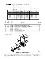
Table 6-1. Drive Roll And Wire Guide Kits
Note
Base selection of drive rolls upon the following recommended usages:
1
V-Grooved rolls for hard wire.
2
U-Grooved rolls for soft and soft shelled cored wires.
3
U-Cogged rolls for extremely soft shelled wires (usually hard surfacing types).
4
V-Knurled rolls for hard shelled cored wires.
5
Drive roll types may be mixed to suit particular requirements (example: V-Knurled roll in combination
with U-Grooved).
Ref. S-0026-B/7-91
Wire Diameter
Fraction
Decimal
Metric
.023/.025 in.
.030 in.
.035 in.
.045 in.
.023/.025 in.
.030 in.
.035 in.
.045 in.
0.6 mm
0.8 mm
0.9 mm
1.2 mm
Kit No.
087 131
079 594
079 595
079 596
Drive Roll
Part No.
Type
087 130
053 695
053 700
053 697
V-Grooved
V-Grooved
V-Grooved
V-Grooved
Inlet
056 192
056 192
056 192
056 193
Wire Guide
1/16 in.
.062
1.6 mm
079 598
053 699
V-Grooved
056 195
.052 in.
.052
1.3 mm
079 597
053 698
V-Grooved
056 193
Description
Part
No.
Dia.
Mkgs.
Item
No.
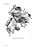
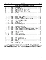
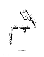
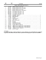
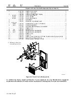
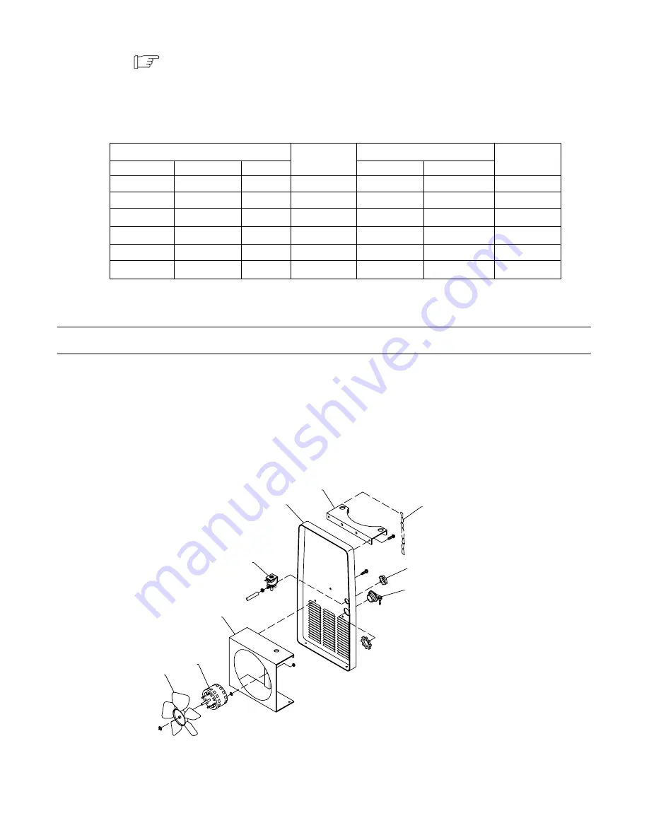
Figure 6-6. Panel, Rear w/Components (Fig 6-1 Item 3)
Quantity
1
148 809
BLADE, fan 9 in 5wg 34deg .309 bore CCW
1
. . .
. . . . . . . . . . .
. . .
. . . . . . . . . . . . . . . . . . . . . . . . . . .
2
FM1
188 706
MOTOR, fan 230V 50/60 Hz 1550RPM .312dia shaft
1
. . .
. . .
. . .
. . .
. . . . . . . . . . . . . . . . . . .
3
188 709
WINDTUNNEL, 9 in
1
. . .
. . . . . . . . . . .
. . .
. . . . . . . . . . . . . . . . . . . . . . . . . . . . . . . . . . . . . . . . . . . . . . . .
4
GS1
125 785
VALVE, 24VAC 2 way custom port 1/8 orf
1
. . .
. . .
. . .
. . .
. . . . . . . . . . . . . . . . . . . . . . . . . . . . .
5
143 810
+PANEL, rear
1
. . .
. . . . . . . . . . .
. . .
. . . . . . . . . . . . . . . . . . . . . . . . . . . . . . . . . . . . . . . . . . . . . . . . . . . . . .
6
169 654
BRACKET, support tank
1
. . .
. . . . . . . . . . .
. . .
. . . . . . . . . . . . . . . . . . . . . . . . . . . . . . . . . . . . . . . . . . . . .
7
188 441
CHAIN, weldless 2/0 x 31.000 lg
1
. . .
. . . . . . . . . . .
. . .
. . . . . . . . . . . . . . . . . . . . . . . . . . . . . . . . . . . . .
8
605 227
NUT, nyl hex jam .750NPST
1
. . .
. . . . . . . . . . .
. . .
. . . . . . . . . . . . . . . . . . . . . . . . . . . . . . . . . . . . . . . . .
9
178 126
CONNECTOR, clamp cable .690/1.070
1
. . .
. . . . . . . . . . .
. . .
. . . . . . . . . . . . . . . . . . . . . . . . . . . . . . .
193 328
LABEL, warning
1
. . . . . . . . . . . . . . . . .
. . .
. . . . . . . . . . . . . . . . . . . . . . . . . . . . . . . . . . . . . . . . . . . . . . . . . . . .
Ref. 802 088-A
.
Hardware is common and
not available unless listed.
1
2
3
4
5
6
7
8
9
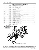
Figure 6-6. Panel, Rear w/Components
+When ordering a component originally displaying a precautionary label, the label should also be ordered.
To maintain the factory original performance of your equipment, use only Manufacturer’s Suggested
Replacement Parts. Model and serial number required when ordering parts from your local distributor.
Summary of Contents for IronMan 275
Page 4: ......
Page 20: ...OM 198 683 Page 16 2 15 Weld Parameter ...
Page 21: ...OM 198 683 Page 17 196 843 VOL TAGE V V WIRE SPEED ...
Page 30: ...OM 198 683 Page 26 Notes ...
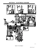
Page 31: ...OM 198 683 Page 27 SECTION 5 ELECTRICAL DIAGRAM 197 699 D Figure 5 1 Circuit Diagram ...
Page 41: ...Notes ...
Page 42: ...Notes ...

