background image

OM-498 Page 6

Le soudage effectué sur des conteneurs fermés tels que
des réservoirs, tambours ou des conduites peut provoquer
leur éclatement. Des étincelles peuvent être projetées de

l’arc de soudure. La projection d’étincelles, des pièces chaudes et des
équipements chauds peut provoquer des incendies et des brûlures. Le contact
accidentel de l’électrode avec des objets métalliques peut provoquer des
étincelles, une explosion, un surchauffement ou un incendie. Avant de
commencer le soudage, vérifier et s’assurer que l’endroit ne présente pas de
danger.

LE SOUDAGE peut provoquer un in-
cendie ou une explosion.

Se protéger et d’autres personnes de la projection d’étincelles et de métal
chaud.

Ne pas souder dans un endroit là où des étincelles peuvent tomber sur des
substances inflammables.

Déplacer toutes les substances inflammables à une distance de 10,7 m de
l’arc de soudage. En cas d’impossibilité les recouvrir soigneusement avec
des protections homologués.

Des étincelles et des matériaux chauds du soudage peuvent facilement
passer dans d’autres zones en traversant de petites fissures et des
ouvertures.

Surveiller tout déclenchement d’incendie et tenir un extincteur à proximité.

Le soudage effectué sur un plafond, plancher, paroi ou séparation peut dé-
clencher un incendie de l’autre côté.

Ne pas effectuer le soudage sur des conteneurs fermés tels que des réser-
voirs, tambours, ou conduites, à moins  qu’ils n’aient  été préparés
correctement conformément à AWS F4.1 (voir les normes de sécurité).

Brancher le câble sur la pièce le plus près possible de la zone de soudage
pour éviter le transport du courant sur une longue distance par des che-
mins inconnus éventuels en provoquant des risques d’électrocution et
d’incendie.

Ne pas utiliser le poste de soudage pour dégeler des conduites gelées.

En cas de non utilisation, enlever la baguette d’électrode du porte-électro-
de ou couper le fil à la pointe de contact.

Porter des vêtements de protection dépourvus d’huile tels que des gants
en cuir, une chemise en matériau lourd, des pantalons sans revers,  des
chaussures hautes et un couvre chef.

Avant de souder, retirer toute substance combustible de vos poches telles
qu’un allumeur au butane ou des allumettes.

DES PARTICULES VOLANTES
peuvent blesser les yeux.

Le soudage, l’écaillement, le passage de la pièce
à la brosse en fil de fer, et le meulage génèrent
des étincelles et des particules métalliques vo-

lantes. Pendant la période de refroidissement des soudures, elles ris-
quent de projeter du laitier.

Porter des lunettes de sécurité avec écrans latéraux ou un écran facial.

LES ACCUMULATIONS DE GAZ ris-
quent de provoquer des blessures ou
même la mort.

Fermer l’alimentation du gaz protecteur en cas de
non utilisation.

Veiller toujours à bien aérer les espaces confinés ou se servir d’un respi-
rateur d’adduction d’air homologué.

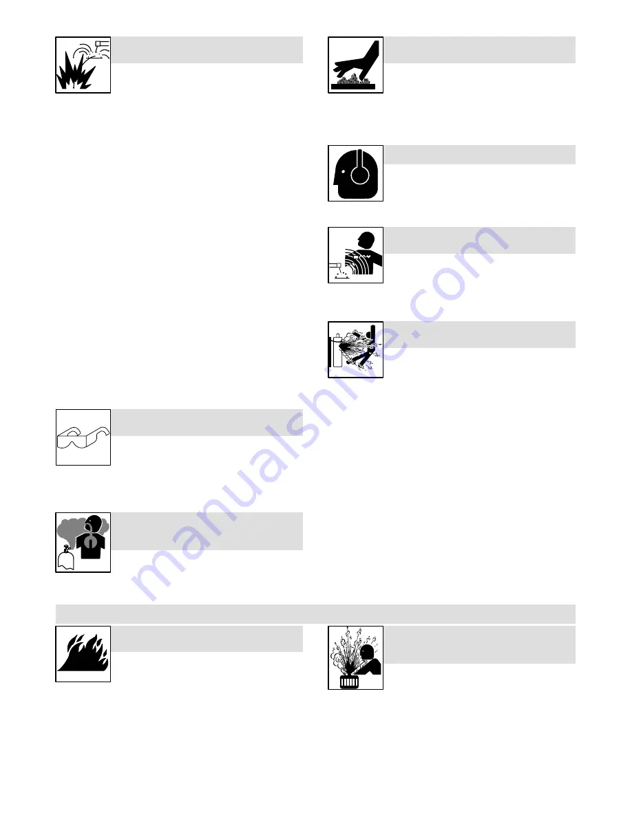
DES PIÈCES CHAUDES peuvent
provoquer des brûlures graves.

Prévoir une période de refroidissement avant d’effec-
tuer des travaux d’entretien.

Porter des gants et des vêtements de protection pour
travailler sur un moteur chaud.

Ne pas toucher à mains nues les parties chaudes du moteur ni les pièces
récemment soudées.

LE BRUIT peut affecter l’ouïe.

Le bruit des processus et des équipements peut affecter
l’ouïe.

Porter des protections approuvés pour les oreilles si
le niveau sondre est trop élevé.

LES CHAMPS MAGNÉTIQUES peuvent
affecter les stimulateurs cardiaques.

Porteurs de stimulateur cardiaque, restez à distance.

Les porteurs d’un stimulateur cardiaque doivent
d’abord consulter leur médecin avant de s’approcher
des opérations de soudage à l’arc, de gougeage ou
de soudage par points.

Si des BOUTEILLES sont endomma-
gées, elles pourront exploser.

Des bouteilles de gaz protecteur contiennent du gaz sous
haute pression. Si une bouteille est endommagée, elle peut
exploser. Du fait que les bouteilles de gaz font normale-
ment partie du procédé de soudage, les manipuler avec
précaution.

Protéger les bouteilles de gaz comprimé  d’une chaleur excessive, des
chocs mécaniques, du laitier, des flammes ouvertes, des étincelles et des
arcs.

Placer les bouteilles debout en les fixant dans un support stationnaire ou
dans un porte-bouteilles pour les empêcher de tomber ou de se renverser.

Tenir les bouteilles éloignées des circuits de soudage ou autres circuits
électriques.

Ne jamais placer une torche de soudage sur une bouteille à gaz.

Une électrode de soudage ne doit jamais entrer en contact avec une bou-
teille.

Ne jamais souder une bouteille pressurisée – risque d’explosion.

Utiliser seulement des bouteilles de gaz protecteur, régulateurs, tuyaux et
raccords convenables pour cette application spécifique; les maintenir ainsi
que les éléments associés en bon état.

Ne pas tenir la tête en face de la sortie en ouvrant la soupape de la bouteille.

Maintenir le chapeau de protection sur la soupape, sauf en cas d’utilisation
ou de branchement de la bouteille.

Lire et suivre les instructions concernant les bouteilles de gaz comprimé,
les équipements associés et les publication P-1 CGA énumérées dans les
normes de sécurité.

1-3.

Dangers existant en relation avec le moteur

LE CARBURANT MOTEUR peut pro-
voquer un incendie ou une explo-
sion.

Arrêter le moteur avant de vérifier le niveau de carbu-
rant ou de faire le plein.

Ne pas faire le plein en fumant ou proche d’une sour-
ce d’étincelles ou d’une flamme nue.

Ne pas faire le plein de carburant à ras bord; prévoir de l’espace pour son
expansion.

Faire attention de ne pas renverser de carburant.  Nettoyer tout carbu-
rant renversé avant de faire démarrer le moteur.

Jeter les chiffons dans un récipient ignifuge.

LA VAPEUR ET LE LIQUIDE DE
REFROIDISSEMENT CHAUD peuvent
provoquer des brûlures.

Il est préférable de vérifier le liquide de
refroidissement une fois le moteur refroidi pour éviter
de se brûler.

Toujours vérifier le niveau de liquide de refroidissement dans le vase
d’expansion (si présent), et non dans le radiateur (sauf si précisé autre-
ment dans la section maintenance du manuel du moteur).

Si le moteur est chaud et que le liquide doit être vérifié, opérer comme
suivant :

Mettre des lunettes de sécurité et des gants, placer un torchon sur le
bouchon


du radiateur.

Dévisser le bouchon légèrement et laisser la vapeur s’échapper avant
d’enlever le bouchon.

Summary of Contents for 1435

Page 1: ...Processes Description Stick SMAW Welding Engine Driven Welding Generator OM 498 197 849D December 2001 CHAMP 1435 Visit our website at www HobartWelders com ...

Page 2: ...e made installation and operation quick and easy With Hobart you can count on years of reliable service with proper maintenance And if for some reason the unit needs repair there s a Troubleshooting section that will help you figure out what the problem is The parts list will then help you to decide which exact part you may need to fix the problem Warranty and service information for your particul...

Page 3: ...G THE WELDING GENERATOR 17 5 1 Controls Kohler Powered Units 17 5 2 Controls Honda Powered Units See Section 5 3 18 5 3 Description Of Controls Honda Powered Units See Section 5 2 19 SECTION 6 OPERATING AUXILIARY EQUIPMENT 20 6 1 Auxiliary Power Panel 196 921 CSA 20 6 2 Optional Auxiliary Power Panels 21 6 3 Auxiliary Power Panel Ratings 22 6 4 Wiring Instructions For Optional 120 240 Volt Twistlo...

Page 4: ......

Page 5: ...en not in use Do not use worn damaged undersized or poorly spliced cables Do not drape cables over your body If earth grounding of the workpiece is required ground it directly with a separate cable Do not touch electrode if you are in contact with the work ground or another electrode from a different machine Use only well maintained equipment Repair or replace damaged parts at once Maintain unit a...

Page 6: ...uch hot engine parts or just welded parts bare handed NOISE can damage hearing Noise from some processes or equipment can damage hearing Wear approved ear protection if noise level is high MAGNETIC FIELDS can affect pacemak ers Pacemaker wearers keep away Wearers should consult their doctor before going near arc welding gouging or spot welding operations Shielding gas cylinders contain gas under h...

Page 7: ...ammables Keep exhaust and exhaust pipes way from flammables EXHAUST SPARKS can cause fire Do not let engine exhaust sparks cause fire Use approved engine exhaust spark arrestor in required areas see applicable codes 1 4 Additional Symbols For Installation Operation And Maintenance FALLING UNIT can cause injury Use lifting eye to lift unit only NOT running gear gas cylinders trailer or any other ac...

Page 8: ...eune Rd Miami FL 33126 National Electrical Code NFPA Standard 70 from National Fire Protec tion Association Batterymarch Park Quincy MA 02269 Safe Handling of Compressed Gases in Cylinders CGA Pamphlet P 1 from Compressed Gas Association 1235 Jefferson Davis Highway Suite 501 Arlington VA 22202 Code for Safety in Welding and Cutting CSA Standard W117 2 from Canadian Standards Association Standards...

Page 9: ...ovoquer une électrocution Mettre l appareil hors tension quand on ne l utilise pas Ne pas utiliser des câbles usés endommagés de grosseur insuffisante ou mal épissés Ne pas enrouler les câbles autour du corps Si la pièce soudée doit être mise à la terre le faire directement avec un câble distinct ne pas utiliser le connecteur de pièce ou le câble de retour Ne pas toucher l électrode quand on est e...

Page 10: ...tection pour travailler sur un moteur chaud Ne pas toucher à mains nues les parties chaudes du moteur ni les pièces récemment soudées LE BRUIT peut affecter l ouïe Le bruit des processus et des équipements peut affecter l ouïe Porter des protections approuvés pour les oreilles si le niveau sondre est trop élevé LES CHAMPS MAGNÉTIQUES peuvent affecter les stimulateurs cardiaques Porteurs de stimula...

Page 11: ...istance les produits inflammables de l échappement LES ÉTINCELLES À L ÉCHAPPEMENT peuvent provoquer un incendie Empêcher les étincelles d échappement du moteur de provoquer un incendie Utiliser uniquement un pare étincelles approuvé voir codes en vigueur 1 4 Dangers supplémentaires en relation avec l installation le fonctionnement et la maintenance LA CHUTE DE L APPAREIL peut blesser Utiliser l an...

Page 12: ...550 N W Lejeune Rd Miami FL 33126 National Electrical Code NFPA Standard 70 de la National Fire Protec tion Association Batterymarch Park Quincy MA 02269 Safe Handling of Compressed Gases in Cylinders CGA Pamphlet P 1 de la Compressed Gas Association 1235 Jefferson Davis Highway Suite 501 Arlington VA 22202 Règles de sécurité en soudage coupage et procédés connexes norme CSA W117 2 de l Associatio...

Page 13: ...een models are noted throughout this manual NOTE 3 1 Weld Power And Engine Specifications Welding Mode Weld Output Range Rated Welding Output Maximum Open Circuit Voltage Auxiliary Power Rating Fuel Capacity Engine CC DC 40 140 A 140 A 25 V 30 Duty Cycle 100 A 25 V 60 Duty Cycle 80 A 25 V 100 Duty Cycle 70 Single Phase 3 5 kVA kW 30 15 A 120 240 V AC 60 Hz Kohler 1 8 gal 6 9 L Tank Honda 1 6 gal 6...

Page 14: ... or operate unit where it C 13 45 64 in 348 mm could tip D 22 3 4 in 577 mm A E 1 3 4 in 44 mm A C F 19 1 2 in 495 mm C G 13 32 in 10 mm Dia Weight Kohler Powered Units 15 15 222 lb 101 kg 4 G 15 15 Weight Honda Powered Units 4 Holes 15 Electric Start Model 226 lb 103 kg F E Recoil Start Model 201 lb 91 kg 802 096 Engine End 802 512 A 3 3 Fuel Consumption Kohler Powered Units 198 573 AUX POWER WEL...

Page 15: ...ng 3 5 Duty Cycle 802 092 Duty cycle is the percentage of 10 minutes that unit can weld at rated load without overheating Exceeding duty cycle can damage unit and void warranty 100 Duty Cycle at 80 Amperes CC DC 3 Minutes Welding 7 Minutes Resting 30 Duty Cycle at 140 Amperes CC DC ...

Page 16: ...eres at the receptacles 3 7 Volt Ampere Curves 198 453 The volt ampere curve shows the minimum and maximum voltage and amperage output capabilities of the welding generator Curves of all other settings fall between the curves shown 0 10 20 30 40 50 60 70 80 0 25 50 75 100 125 150 175 200 LOAD AMPS LOAD VOLTS MIN MID MAX ...

Page 17: ...uck Or Trailer Frame install1 1 97 Ref 151 556 S 0854 Always ground generator frame to vehicle frame to pre vent electric shock and static electricity hazards 1 Generator Base 2 Metal Vehicle Frame 3 Equipment Grounding Terminal 4 Grounding Cable Use 10 AWG or larger insulated copper wire If unit does not have GFCI receptacles use GFCI protected extension cord 1 2 Electrically bond generator frame...

Page 18: ...evel shut down switch However some conditions may cause engine damage before the engine shuts down Check oil level often and do not use the oil level shutdown system to monitor oil level 1 Fuel Valve Open valve by turning lever to verti cal position Close fuel valve before moving unit or carburetor may flood and make starting difficult Fuel Add fresh fuel before starting engine the first time see ...

Page 19: ...te nance label for specifications Fill fuel tank up to 1 2 in 13 mm from top to allow room for expansion Check fuel level on a cold engine before use each day Oil After fueling check oil with unit on level surface If oil is not up to full mark on dipstick add oil see main tenance label To improve cold weather starting Keep battery in good condition Store battery in warm area off concrete surface U...

Page 20: ...nnectingto weld out put terminals Do not use worn dam aged undersized or poorly spliced cables Welding Amperes 10 60 Duty Cycle 60 100 Duty Cycle 10 100 Duty Cycle 100 4 20 4 20 4 20 3 30 2 35 1 50 1 0 60 1 0 60 150 3 30 3 30 2 35 1 50 1 0 60 2 0 70 3 0 95 3 0 95 200 3 30 2 35 1 50 1 0 60 2 0 70 3 0 95 4 0 120 4 0 120 250 2 35 1 50 1 0 60 2 0 70 3 0 95 4 0 120 2 ea 2 0 2x70 2 ea 2 0 2x70 This char...

Page 21: ... 4 Starter Handle To Start open fuel valve see Section 4 4 turn engine switch to On move throttle lever to Idle set choke and pull starter handle Open choke as engine warms To Stop turn engine switch to Off Always close fuel valve after stopping unit Moving unit with fuel valve open may cause carburetor flooding and make starting difficult 5 Welding Range Label Use label to determine correct weld ...

Page 22: ...OM 498 Page 18 5 2 Controls Honda Powered Units See Section 5 3 802 099 A 802 100 A 953T 5 4 Recoil Start Electric Start 60 Hz 1 4 3 6 2 1 5 ...

Page 23: ... throttle lever to Idle set choke and pull starter handle Open choke as engine warms To Start Electric open fuel valve move throttle lever to Idle set choke and turn en gine switch to Start position Open choke as engine warms If the engine does not start let engine come to a complete stop before at tempting restart To Stop turn engine switch to Off Always close fuel valve after stopping unit Movin...

Page 24: ... Receptacle RC1 RC1 supplies 60 Hz single phase power at weld power speed Maximum output is 3 5 kVA kW 2 120 V 20 A AC Duplex Receptacle RC2 3 120 V 20 A AC Duplex Receptacle RC3 RC2 and RC3 supply 60 Hz single phase power at weld power speed Maximum output from RC2 or RC3 is 2 4 kVA kW Each receptacle of the duplex can pro vide 15A 1800W Do not parallel the two 120V duplex receptacles 4 Circuit B...

Page 25: ...it breaker trips Unplug power cord before attempt ing to service accessories or tools Auxiliary power decreases as weld current increases Set Amperage control at max for full auxiliary power Place throttle lever in Run position far right for auxiliary power Circuit breakers protect the generator from overload Press button to reset circuit breaker If breaker continues to open contact Factory Author...

Page 26: ...x CB3 20A 2400W 20A 2400W See Note 3 20A 2400W 120 V Duplex CB4 20A 2400W See Note 3 20A 2400W Total Power NOT to exceed 3500W 3500W 3500W 3500W 3500W 3500W 3500W 3500W 3500W For example for the 495 218 Auxiliary Power Panel 120V 1500W heater 1500W 120V 10A chain saw 1200W 120V 500W halogen lamp 500W Total 3200W This loading is OK 120V 1500W heater 1500W 120V 10A chain saw 1200W 120V 5A router 600...

Page 27: ...ne half of the 240 V receptacle 2 Neutral Silver Terminal 3 Load 1 Brass Terminal 4 Load 2 Brass Terminal 5 Ground Green Terminal 6 Cord Grip Strip cord jacket back enough to sep arate conductors Strip conductors enough to make good contact with plug terminals Make plug connections and reinstall outer shell and cord grip Tighten assembly screws onto shell Do not overtighten 1 3 2 4 Tools Needed 5 ...

Page 28: ...n See engine manual 50 h Clean and tighten weld terminals Service air cleaner element See engine manual 100 h Change oil See engine manual and maintenancelabel Check spark plugs Clean and tighten battery connections Electric Start models only Clean Fuel sediment cup 200 h Replace unreadable labels Clean fuel tank and strainer 300 h Check valve clearance 500 h Repair or replace cracked cables Servi...

Page 29: ...20 10 0 40 C 104 10 10 15 20 200 h 0 7 0 8 mm 0 028 0 031 in SG SF CC CD 7 3 Overload Protection Honda Powered Units Only 1 Ignition Circuit Breaker Electric Start Models Only The circuit breaker protects the en gine battery charging circuit A short circuit or a battery connected in reverse polarity will trip the circuit breaker Press button to reset breaker If a switch or breaker opens it usually...

Page 30: ...l Lever 2 Adjustment Screw Move lever to Run far right posi tion To increase speed turn screw out counterclockwise while lightly pushing lever to the right To de crease speed turn screw in clock wise Idle Speed Adjustment 3 Adjustment Screw Move lever to idle far left position To increase idle speed turn screw in clockwise To decrease idle speed turn screw out counter clockwise Stop engine Close f...

Page 31: ...trol Lever 2 Adjustment Screw Move lever to Run far left position Turn screw and move lever until en gine runs at weld power speed Idle Speed Adjustment 3 Pilot Screw 4 Throttle Stop Screw Move lever to idle far right posi tion Turn pilot screw until engine runs at highest idle speed Turn stop screw until engine runs at rated idle speed normally about 2 1 4 turns out Stop engine Close fuel valve 1...

Page 32: ...s for Stick welding Remove excessive coils from weld cables Clean and tighten connections both inside and outside welding generator Check engine speed and adjust if necessary see Section 7 4 or 7 5 Check throttle governor linkage for smooth non binding operation B Auxiliary Power Trouble Remedy No output at auxiliary power receptacles Reset circuit breakers see Section 6 1 Check receptacle wiring ...

Page 33: ...s too low Refill crankcase with proper viscosity oil for operating temperature Have Factory Authorized Service Agent check low oil level shutdown switch Engine stopped during normal operation Check fuel level see Section 4 4 or 4 5 Open fuel valve see Section 4 4 or 4 5 Close fuel valve before moving unit or carburetor may flood and make starting difficult Check oil level see Section 4 4 or 4 5 En...

Page 34: ...OM 498 Page 30 SECTION 9 ELECTRICAL DIAGRAMS SC 495 297 198 016 D Figure 9 1 Circuit Diagram For Welding Generator ...

Page 35: ...OM 498 Page 31 198 014 C Figure 9 2 Wiring Diagram For Welding Generator ...

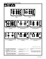
Page 36: ...OM 498 Page 32 201 026 A Figure 9 3 Wiring Diagram For Auxiliary Power Panels 1 Of 2 ...

Page 37: ...OM 498 Page 33 201 026 A Figure 9 4 Wiring Diagram For Auxiliary Power Panels 2 Of 2 ...

Page 38: ...le Insulated Equipment OR 2 Be sure equipment has this symbol and or wording 3 1 10 2 Grounding Generator To Truck Or Trailer Frame S 0854 1 Generator Base 2 Metal Vehicle Frame 3 Equipment Grounding Terminal 4 Grounding Cable Use 10 AWG or larger insulated copper wire If unit does not have GFCI re ceptacles use GFCI pro tected extension cord OR 1 2 Electrically bond generator frame to vehicle fra...

Page 39: ...sistive Load Equipmentwith a motor is a non re sistive load and requires approxi mately six times more power while starting the motor than when run ning see Section 10 8 3 Rating Data Rating shows volts and amperes or watts required to run equipment VOLTS 115 4 5 60 AMPS Hz 1 2 3 3 EXAMPLE 1 If a drill uses 4 5 amperes at 115 volts calculate its running power requirementin watts 4 5 A x 115 V 520 ...

Page 40: ...Home Equipment Rating Starting Watts Running Watts Stock Tank De Icer 1000 1000 Grain Cleaner 1 4 HP 1650 650 Portable Conveyor 1 2 HP 3400 1000 Grain Elevator 3 4 HP 4400 1400 Milk Cooler 2900 1100 Milker Vacuum Pump 2 HP 10500 2800 FARM DUTY MOTORS 1 3 HP 1720 720 Std e g Conveyors 1 2 HP 2575 975 Feed Augers Air 3 4 HP 4500 1400 Compressors 1 HP 6100 1600 1 1 2 HP 8200 2200 2 HP 10550 2850 3 HP...

Page 41: ...HP 6000 1500 1 1 2 HP 8200 2200 2 HP 10500 2800 Electric Chain Saw 1 1 2 HP 12 in 1100 1100 2 HP 14 in 1100 1100 Electric Trimmer Standard 9 in 350 350 Heavy Duty 12 in 500 500 Electric Cultivator 1 3 HP 2100 700 Elec Hedge Trimmer 18 in 400 400 Flood Lights HID 125 100 Metal Halide 313 250 Mercury 1000 Sodium 1400 Vapor 1250 1000 Submersible Pump 400 gph 600 200 Centrifugal Pump 900 gph 900 500 F...

Page 42: ...r Starting Requirements Motor Start Code G H J K L M N P KVA HP 6 3 7 1 8 0 9 0 10 0 11 2 12 5 14 0 EXAMPLE Calculate the starting amperage required for a 230 V 1 4 HP motor with a motor start code of M Starting the motor requires 12 2 amperes 11 2 x 1 4 x 1000 230 12 2 A kVA HP x HP x 1000 VOLTS STARTING AMPERAGE Volts 230 HP 1 4 Using Table Code M results in kVA HP 11 2 10 9 How Much Power Can G...

Page 43: ...nnections Connect terminals or plug of ade quate amperage capacity to cord Follow all applicable codes and safety practices Turn off or unplug all equipment connected to generator before starting or stopping engine When starting or stopping the engine has low speed which causes low volt age and frequency 7 Load Connections Customer supplied equipment is required if generator is to supply standby p...

Page 44: ... 15 40 4800 112 34 62 19 37 11 45 5400 100 30 62 19 50 6000 87 26 50 15 Conductor size is based on maximum 2 voltage drop Cord Lengths for 240 Volt Loads If unit does not have GFCI receptacles use GFCI protected extension cord Maximum Allowable Cord Length in ft m for Conductor Size AWG Current Amperes Load Watts 4 6 8 10 12 14 5 1200 700 213 450 137 225 84 200 61 7 1680 800 244 500 152 300 91 200...

Page 45: ...is clean be fore welding 2 Work Clamp 3 Electrode A small diameter electrode requires less current than a large one Fol low electrode manufacturer s instructions when setting weld am perage see Section 11 2 4 Insulated Electrode Holder 5 Electrode Holder Position 6 Arc Length Arc length is the distance from the electrode to the workpiece A short arc with correct amperage will give a sharp cracklin...

Page 46: ...LLET ALL ALL EP EP EP EN EP EN EP EP EN EP EP 6010 6011 6013 7014 7018 7024 NI CL 308L EP ELECTRODE POSITIVE REVERSE POLARITY EN ELECTRODE NEGATIVE STRAIGHT POLARITY ELECTRODE AMPERAGE RANGE DIAMETER 11 3 Striking an Arc Scratch Start Technique S 0049 1 Electrode 2 Workpiece 3 Arc Drag electrode across workpiece like striking a match lift electrode slightly after touching work If arc goes out elec...

Page 47: ... 11 6 Poor Weld Bead Characteristics S 0053 A 1 Large Spatter Deposits 2 Rough Uneven Bead 3 Slight Crater During Welding 4 Bad Overlap 5 Poor Penetration 5 4 2 3 1 11 7 Good Weld Bead Characteristics S 0052 B 1 Fine Spatter 2 Uniform Bead 3 Moderate Crater During Welding Weld a new bead or layer for each 1 8 in 3 2 mm thickness in metals being welded 4 No Overlap 5 Good Penetration into Base Meta...

Page 48: ...Correct Angle 11 9 Electrode Movement During Welding Normally a single stringer bead is satisfactory for most narrow groove weld joints however for wide groove weld joints or bridging across gaps a weave bead or multiple stringer beads work better NOTE S 0054 A 1 Stringer Bead Steady Movement Along Seam 2 Weave Bead Side to Side Movement Along Seam 3 Weave Patterns Use weave patterns to cover a wi...

Page 49: ...3 4 11 11 Lap Joint S 0063 S 0064 1 Electrode 2 Single LayerFillet Weld Move electrode in circular motion 3 Multi Layer Fillet Weld Weld a second layer when a heavi er fillet is needed Remove slag be fore making another weld pass Weld both sides of joint for maxi mum strength 30 Or Less Single Layer Fillet Weld Multi Layer Fillet Weld 30 Or Less 1 1 2 3 11 12 Tee Joint S 0060 S 0058 A S 0061 1 Ele...

Page 50: ... Causes Corrective Actions Arc length too long Reduce arc length Damp electrode Use dry electrode Workpiece dirty Remove all grease oil moisture rust paint coatings slag and dirt from work surface before welding 11 15 Troubleshooting Excessive Spatter Excessive Spatter scattering of molten metal particles that cool to solid form near weld bead Possible Causes Corrective Actions Amperage too high f...

Page 51: ... dirt from work surface before welding 11 17 Troubleshooting Lack Of Penetration Lack Of Penetration shallow fusion between weld metal and base metal Lack of Penetration Good Penetration Possible Causes Corrective Actions Improper joint preparation Material too thick Joint preparation and design must provide access to bottom of groove Improper weld technique Keep arc on leading edge of weld puddle...

Page 52: ...allel and does not cover joint formed by base metal Possible Causes Corrective Actions Unsteady hand Use two hands Practice technique 11 21 Troubleshooting Distortion Distortion contraction of weld met al during welding that forces base metal to move Base metal moves in the direction of the weld bead Possible Causes Corrective Actions Excessive heat input Use restraint clamp to hold base metal in ...

Page 53: ...OM 498 Page 49 Notes ...

Page 54: ...LIST Hardware is common and not available unless listed 802 513 A 802 153 B 19 25 29 22 23 28 26 27 20 21 32 33 30 31 Fig 12 2 34 35 37 36 1 6 24 3 5 4 7 8 2 18 17 16 15 14 13 12 9 11 10 38 39 40 41 42 43 44 Figure 12 1 Main Assembly ...

Page 55: ...48 SCREW 5 16 24 HWH 1 19 494 628 PANEL end generator 1 20 495 113 LEAD bonding 1 21 495 257 MOUNT shock w bushing 2 22 495 256 MOUNT shock generator 1 23 194 504 FRAME mtg assembly Kohler 1 23 495 132 FRAME mtg assembly Honda 1 24 PC1 148 608 BOARD PC filter CSA only 1 25 494 613 TERMINAL output 2 26 R1 494 618 RHEOSTAT 35 ohm 100W 1 27 495 214 SEAL air duct 1 28 495 255 DUCT air 1 29 097 924 KNO...

Page 56: ...y Power Panel 495 279 Canada Auxiliary Power Panel 495 253 South Africa Auxiliary Power Panel 495 289 Australia 6 7 8 9 10 11 12 13 14 15 16 18 17 17 19 19 20 21 22 23 Auxiliary Power Panel 495 290 Europe Auxiliary Power Panel 495 288 S America Auxiliary Power Panel 495 283 S E Asia 24 25 Auxiliary Power Panel 495 298 USA 1 Figure 12 2 Auxiliary Power Panels ...

Page 57: ...RCUIT BREAKER 30A 1 15 CB2 CB3 495 246 CIRCUIT BREAKER 20A 2 Auxiliary Power Panel 495 253 South Africa 16 495 252 PANEL auxiliary power assembly 1 17 CB1 CB2 495 245 CIRCUIT BREAKER 15A 2 Auxiliary Power Panel 495 289 Australia 18 495 254 PANEL auxiliary power assembly 1 19 CB1 CB4 495 245 CIRCUIT BREAKER 15A 4 Auxiliary Power Panel 495 290 Europe 20 495 282 PANEL auxiliary power assembly 1 21 CB...

Page 58: ...OM 498 Page 54 Notes ...

Page 59: ...obart s 5 3 1 Limited Warranty shall not apply to 1 Consumable components such as contact tips cutting nozzles slip rings drive rolls gas diffusers plasma torch tips and electrodes weld cables and tongs and tips or parts that fail due to normal wear 2 Items furnished by Hobart Miller but manufactured by others such as engines or trade accessories These items are covered by the manufacturer s warra...

Page 60: ...r To locate a Distributor retail or service location Call 1 877 Hobart1 or visit our website at www HobartWelders com Contact your Distributor for Welding Supplies and Consumables Options and Accessories Personal Safety Equipment Service and Repair Replacement Parts Training Schools Videos Books Technical Manuals Servicing Information and Parts Circuit Diagrams Welding Process Handbooks Contact th...

Reviews: