OM-498 Page 22
6-3.
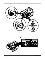
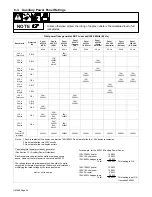
Auxiliary Power Panel Ratings
Unless otherwise stated, the rating of duplex outlets is the combined load of all
receptacles.
NOTE
Total power from generator NOT to exceed 3500 Watts (60 Hz)
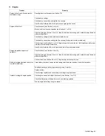
Receptacle
Protected
By
Panel
495 218
(USA)
Panel
495 315
(USA)
Panel
495 298
(USA)
Panel
495 279
(Canada-
CSA)
Panel
495 253
(S. Africa)
Panel
495 288
(South
America)
Panel
495 289
(Australia)
Panel
495 290
(Europe)
Panel
495 283
(S.E. Asia)
60 Hz
60 Hz
60 Hz
60 Hz
60 Hz
60 Hz
60 Hz
60 Hz
60 Hz
240 V
Twist Lock
CB1,2
30A/
3600W
240 V
Duplex
CB1,2
15A/
3500W
See
Note 2
15A/
3500W
240 V
Duplex
CB3,4
15A/
3500W
230 V
Single
CB1
15A/
3500W
15A/
3500W
15A/
3500W
230 V
Single
CB2
15A/
3500W
15A/
3500W
15A/
3500W
230 V
Single
CB1,2
15A/
3500W
230 V
Single
CB3,4
15A/
3500W
120 V
Twist Lock
CB1
30A/
3500W
30A/
3500W
120 V
Duplex
CB1,2
CB1,3
30A/
3500W
120 V
Duplex
CB2
20A/
2400W
120 V
Duplex
CB3
20A/
2400W
20A/
2400W
See
Note 3
20A/
2400W
120 V
Duplex
CB4
20A/
2400W
See
Note 3
20A/
2400W
Total
Power NOT
to exceed
3500W
3500W
3500W
3500W
3500W
3500W
3500W
3500W
3500W
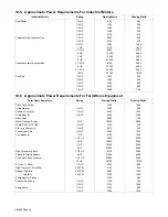
For example, for the 495 218 Auxiliary Power Panel,
120V, 1500W heater
1500W
120V, 10A chain saw
1200W
120V, 500W halogen lamp
500W
Total
3200W
This loading is OK.
120V, 1500W heater
1500W
120V, 10A chain saw
1200W
120V, 5A router
600W
120V, 500W halogen lamp
500W
Total
3800W
This loading is not OK.
It exceeds 3500W.
Notes: 1. Each receptacle of the duplex can provide 15A/1800W. Do not parallel the two 120V duplex receptacles.
2. Do not parallel the two 120V circuits.
3. Do not parallel the two duplex outlets.
Calculating total power provided by generator.
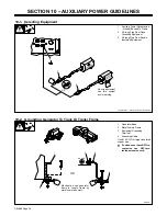
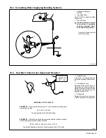
(See Section 10 – Auxiliary Power Guidelines)
Each receptacle can provide the watts or amps as shown
above. However, the total power can not exceed 3500W.
The rating plate on electrical apparatus will contain the watts
consumed or the rated input amps. Watts may be calculated by
multiplying the rated voltage by the rated input amps.
watts = volts x amps
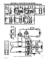
Summary of Contents for 1435
Page 4: ......
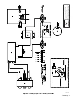
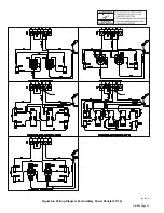
Page 35: ...OM 498 Page 31 198 014 C Figure 9 2 Wiring Diagram For Welding Generator ...
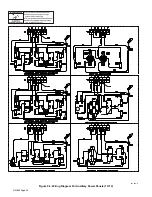
Page 36: ...OM 498 Page 32 201 026 A Figure 9 3 Wiring Diagram For Auxiliary Power Panels 1 Of 2 ...
Page 37: ...OM 498 Page 33 201 026 A Figure 9 4 Wiring Diagram For Auxiliary Power Panels 2 Of 2 ...
Page 53: ...OM 498 Page 49 Notes ...
Page 58: ...OM 498 Page 54 Notes ...

