background image

OM-260 274 Page 39

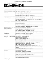
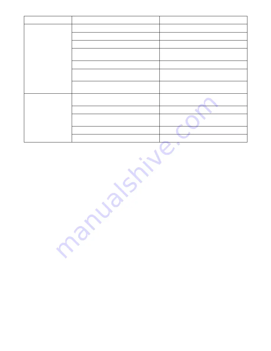
Problem

Remedy

Probable Cause

Wire feeds, but no gas flows. Gas cylinder empty.

Replace empty gas cylinder.

Gas nozzle plugged.

Clean or replace gas nozzle.

Gas cylinder valve not open or flowmeter not adjusted. Open gas valve at cylinder and adjust flow rate.

Restriction in gas line.

Check gas hose between flowmeter and wire feeder, and

gas hose in gun and cable assembly.

Loose or broken wires to gas solenoid.

Have Factory Authorized Service Agent repair wiring.

Gas solenoid valve not operating.

Have Factory Authorized Service Agent replace gas

solenoid valve.

Incorrect primary voltage connected to welding power

source.

Check primary voltage and relink welding power source

for correct voltage.

Welding arc not stable.

Wire slipping in drive rolls.

Adjust pressure setting on wire feed rolls. Replace worn

drive rolls if necessary.

Wrong size gun liner or contact tip.

Match liner and contact tip to wire size and type.

Incorrect voltage setting for selected wire feed speed on

welding power source.

Readjust welding parameters.

Loose connections at the gun weld cable or work cable. Check and tighten all connections.

Gun in poor shape or loose connection inside gun.

Repair or replace gun as necessary.

Summary of Contents for 210 MVP

Page 1: ...www HobartWelders com OM 260 274C 2013 06 Processes Arc Welding Power Source And Wire Feeder Description MIG GMAW Welding Flux Cored FCAW Welding File MIG GMAW R Handler 210 MVP And H100S4 10 Gun ...

Page 2: ... 2 Installing Nozzle Contact Tip And Adapter 14 5 3 Installing Work Clamp 14 5 4 Installing Welding Gun 15 5 5 Process Polarity Table 15 5 6 Changing Polarity 15 5 7 Installing Gas Supply 16 5 8 Electrical Service Guide 17 5 9 Extension Cord Data Use Shortest Cord Possible 17 5 10 Multi Voltage Plug MVP Connection 18 5 11 Connecting Input Power 19 5 12 Connecting 1 Phase Input Power For 230 VAC In...

Page 3: ...lds when in cramped positions such as sitting kneeling or lying or when there is a high risk of unavoid able or accidental contact with the workpiece or ground For these conditions use the following equipment in order presented 1 a semiautomaticDC constant voltage wire welder 2 a DC manual stick welder or 3 an AC welder with reduced open circuit volt age In most situations use of a DC constant vol...

Page 4: ...rums or pipes unless they are properly prepared according to AWS F4 1 and AWS A6 0 see Safety Standards D Do not weld where the atmosphere may contain flammable dust gas or liquid vapors such as gasoline D Connect work cable to the work as close to the welding area as practical to prevent welding current from traveling long possibly unknown paths and causing electric shock sparks and fire hazards ...

Page 5: ...ING PARTS can injure D Keep away from moving parts such as fans D Keep all doors panels covers and guards closed and securely in place D Have only qualified persons remove doors panels covers or guards for maintenance and troubleshooting as necessary D Reinstall doors panels covers or guards when maintenance is finished and before reconnecting input power READ INSTRUCTIONS D Read and follow all la...

Page 6: ...ention During Welding Cutting and Other Hot Work NFPA Standard 51B from National Fire Protection Association Quincy MA 02269 phone 1 800 344 3555 website www nfpa org OSHA Occupational Safety and Health Standards for General Indus try Title 29 Code of Federal Regulations CFR Part 1910 Subpart Q and Part 1926 Subpart J from U S Government Printing Office Super intendentof Documents P O Box 371954 P...

Page 7: ...électrique à courant électrique s avère nécessaire se servir de la fonction de télécommande si l appareil en est équipé D D autres consignes de sécurité sont nécessaires dans les condi tions suivantes risques électriques dans un environnement humideou si l on porte des vêtements mouillés sur des structures métalliquestelles que sols grilles ou échafaudages en position coincée comme assise à genoux...

Page 8: ...aine et des bottes de protection LE SOUDAGE peut provoquer un incendie ou une explosion Le soudage effectué sur des conteneurs fermés tels que des réservoirs tambours ou des conduites peut provoquer leur éclatement Des étincelles peuvent être projetées de l arc de soudure La projection d étincelles des pièces chaudes et des équipements chauds peut provoquer des incendies et des brûlures Le contact...

Page 9: ...D Utiliser les équipements corrects les bonnes procédures et suffi samment de personnes pour soulever et déplacer les bouteilles D Lire et suivre les instructions sur les bouteilles de gaz comprimé l équipement connexe et le dépliant P 1 de la CGA Compressed Gas Association mentionné dans les principales normes de sécu rité 2 3 Dangers supplémentaires en relation avec l installation le fonctionnem...

Page 10: ...à des personnes qualifiées familiarisées avec des équipements électroniques de faire fonctionner l installa tion D L utilisateur est tenu de faire corriger rapidement par un électricien qualifié les interférences résultant de l installation D Si le FCC signale des interférences arrêter immédiatement l ap pareil D Effectuer régulièrement le contrôle et l entretien de l installation D Maintenir soig...

Page 11: ... Part 1926 Subpart J from U S Government Printing Office Super intendentof Documents P O Box 371954 Pittsburgh PA 15250 7954 phone 1 866 512 1800 there are 10 OSHA Regional Offices phone for Region 5 Chicago is 312 353 2220 website www osha gov Applications Manual for the Revised NIOSH Lifting Equation The Na tional Institute for Occupational Safety and Health NIOSH 1600 Clifton Rd Atlanta GA 3033...

Page 12: ...ertz Negative Positive Direct Current DC Single Phase Input Output Voltage Input Off On Do Not Switch While Welding Gas Metal Arc Welding GMAW Wire Feed Circuit Protector U0 Rated No Load Voltage Average U1 Primary Voltage U2 Conventional Load Voltage Line Connection I1max Rated Maximum Supply Current I2 Rated Welding Current X Duty Cycle Single Phase Transformer Rectifier Temperature Increase Per...

Page 13: ... 36 kg Length 19 1 2 in 495 mm Width 10 5 8 in 273 mm Height 12 3 8 in 314 mm Wire Type And Diameter Solid Stainless Flux Cored Aluminum Wire Feed Speed Range 023 035 in 0 6 0 9 mm 030 045 in 0 8 1 2 mm 030 035 in 0 8 0 9 mm 70 750 IPM 1 8 19 0 m min At No Load 40 680 IPM 1 0 17 3 m min Feeding Wire 4 3 Unit Specifications For 115 VAC Rated Welding Output Amperage Range Maximum Open Circuit Voltag...

Page 14: ...ts thermostat s opens output stops and cooling fan runs Wait fifteen minutes for unit to cool Reduce amperage or duty cycle before welding NOTICE Exceeding duty cycle can damage unit or gun and void warranty Overheating 0 15 A or V OR Reduce Duty Cycle Minutes duty1 4 95 249 620 A 30 duty cycle at 150 amps 3 Minutes Welding 7 Minutes Resting 230 VAC 20 duty cycle at 90 amps 2 Minutes Welding 8 Min...

Page 15: ...tput capabilities of the welding power source Curves of other settings fall between the curves shown ssb1 1 10 91 249 621 A 0 5 10 15 20 25 30 0 10 20 30 40 50 60 70 80 90 100 110 120 130140 150 160 170 180190 200 210 220 35 Voltage Amperage 1 2 3 4 5 6 7 230 VAC 0 5 10 15 20 25 30 0 10 20 30 40 50 60 70 80 90 100 110 120 130 140 150 160 170 35 Voltage Amperage 5 4 6 7 115 VAC ...

Page 16: ...E 5 2 Installing Nozzle Contact Tip And Adapter Ref 243 839 A Turn off welding power source 1 Nozzle 2 Contact Tip 3 Tip Adapter Wire size stamped on tip check and match wire size Tools Needed 8 mm Head Tube 8 mm 1 3 2 5 3 Installing Work Clamp 258 550 A 1 2 3 4 5 6 1 Work Clamp 2 Work Cable From Unit 3 Screw 4 Flat Washer 5 Lock Washer 6 Nut Route work cable through hole in clamp handle Secure ca...

Page 17: ...d O rings will cause shielding gas leakage Spool Gun MIG Gun 6 ÉÉ ÉÉ ÉÉ 5 1 3 2 4 5 5 Process Polarity Table Process Polarity Cable Connections Cable To Gun Cable To Work GMAW Solid wire with shielding gas DCEP Reverse polarity Connect to positive output terminal Connect to negative output terminal FCAW Self shielding wire no shielding gas DCEN Straight Polarity Connect to negative output terminal...

Page 18: ...nnect supplied gas hose between regulator flowmeter gas hose connection and fitting on rear of welding power source 7 Flow Adjust Flow rate should be set when gas is flowing through welding power source and welding gun Open pressure assembly so that wire will not feed Press gun trigger to start gas flow Typical flow rate is 20 cfh cubic feet per hour Check wire manufacturer s recommended flow rate...

Page 19: ...or Size In AWG 4 14 Max Recommended Input Conductor Length In Feet Meters 53 16 Min Grounding Conductor Size In AWG 4 14 Reference 2011 National Electrical Code NEC including article 630 1 If a circuit breaker is used in place of a fuse choose a circuit breaker with time current curves comparable to the recommended fuse 2 Time Delay fuses are UL class RK5 See UL 248 3 Normal Operating general purp...

Page 20: ...tacle NEMA Type 6 50R Customer Supplied Follow electrical service guide for 230 VAC in Section 5 8 Do not use plug rating to size branch circuit protection Connecting Plug To Power Cord Align arrow on plug with arrow on power cord connector Push together Tighten threaded collar As threaded collar is tightened push plug onto adapter until collar is completely tight Connect plug to receptacle MVP Pl...

Page 21: ...ion 4 1 For 115 VAC input power a 20 ampere individual branch circuit protected by time delay fuses or circuit breaker is required see Section 5 13 For 230 VAC input power see Section 5 12 1 Power Cord Connector 2 Plug NEMA Type 5 15P 3 Receptacle NEMA Type 5 15R Customer Supplied 4 Plug NEMA Type 5 20P Optional 5 Receptacle NEMA Type 5 20R Customer Supplied 6 Plug NEMA Type 6 50P 7 Receptacle NEM...

Page 22: ...minal See rating label on unit and check input volt age available at site 1 Input Power Cord 2 Disconnect Device switch shown in the OFF position 3 Disconnect Device Grounding Terminal 4 Disconnect Device Line Terminals 5 Black And White Input Conductor L1 And L2 6 Green Or Green Yellow Grounding Conductor Connect green or green yellow grounding conductor to disconnect device grounding terminal fi...

Page 23: ...ircuit protected by time delay fuses or circuit breaker is required 1 Multi Voltage Plug And Power Cord Connector NEMA Type 5 15P Plug Shown For multi voltage plug connections see Section 5 11 2 Receptacle NEMA Type 5 15R Customer Supplied 2 1 5 14 Installing Wire Spool And Adjusting Hub Tension When a slight force is needed to turn spool tension is set 1 2 in Tools Needed 803 012 803 013 B Ref 80...

Page 24: ...r polarity connection see welding power source Owner s Manual Close door 8 Wire Feed Speed Control Wire feed speed is controlled by welding power source Wire Speed control see welding power source Owner s Manual or door chart for appropriatesetting 9 Voltage Control Arc voltage is controlled by welding power source Voltage control see welding power source Owner s Manual or door chart for appropria...

Page 25: ... it from unraveling 260 587 A WOOD Feed wire to check drive roll pressure Tighten knob enough to prevent slipping Cut off wire Close door Press gun trigger until wire comes out of gun Turn power on Be sure that Voltage range switch is set to range 1 2 3 4 5 6 or 7 to feed wire Rotate knob until it clicks into detent Wire will not feed if range switch is set between ranges 6 in 150 mm Tighten Use p...

Page 26: ...s unit from overload If CB1 opens unit shuts down Reset power switch supplementary protector 3 Voltage Control Control varies the voltage level of the welding arc The voltage range is 4 minimum to 7 maximum on 115 VAC and 1 minimum to 7 maximum on 230 VAC Switch must click into detent position DO NOT switch under load 4 Over Temperature Light Light illuminates if main transformer overheats 5 Gun T...

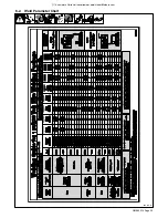
Page 27: ... A complete Parts List is available at www HobartWelders com OM 260 274 Page 25 6 2 Weld Parameter Chart 250 015 B ...

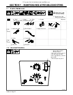
Page 28: ...nge Clean l Replace To be done by Factory Authorized Service Agent Reference Every 3 Months l Unreadable Labels Weld Terminals l Damaged Gas Hose nl Weld Cables nl Cords nl Gun Cables Every 6 Months OR Drive Rolls Inside Unit 7 2 Overload Protection 250 653 A 1 SupplementaryProtector CB1 Power Switch CB1 protects unit from overload If CB1 opens unit shuts down Reset supplementary protector power s...

Page 29: ...to thread see Section 5 16 VK Knurled groove is used for flux cored wire and V groove is used for solid wire 4 Retaining Pin To secure drive roll locate open slot and push drive roll completely over retaining pin then rotate drive roll 1 4 turn to closed slot 5 Drive Roll Tension Knob Using flux core wire with VK groove tension should be set between 1 1 2 to 2 Higher setting may cause welding wire...

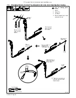
Page 30: ...size stamped on tip check and match wire size Tools Needed 8 mm 10 mm Lay gun cable out straight before installing new liner Remove nozzle contact tip and adapter Unscrew and remove liner Blow out gun casing Cut off wire and disconnect gun from feeder 5 8 in 16 mm Liner Stickout Install Liner Reassemble gun in reverse order from taking it apart 10 mm Head Tube 8 mm 1 3 2 Thread wire according to w...

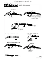
Page 31: ... Remove from vice Reposition handle halves and install switch housing Turn Off welding power source wire feeder and disconnect gun Remove switch housing Install new switch and connect leads polarity is not important Reassemble in reverse order If replacing head tube continue to end of figure 1 2 3 8 6 7 Remove screw on opposite side Secure head tube in vice Loosen jam nut Remove from vice and turn...

Page 32: ...Check and if necessary replace gun trigger switch see Section 7 6 Check contact tip Check for kinks in gun cable Blow out liner and gun casing see Section 7 5 Low weld output Connect unit to proper input voltage or check for low line voltage Place voltage switch in desired position see Section 6 1 Electrode wire feeding stops during welding Straightengun cable and or replace damaged parts Adjust d...

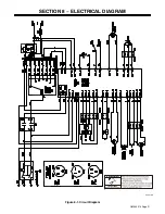
Page 33: ...OM 260 274 Page 31 SECTION 8 ELECTRICAL DIAGRAM 249 315 A Figure 8 1 Circuit Diagram ...

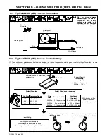
Page 34: ... comply to specifications 3 5 x 125 A 437 ipm 2 x 125 A 250 ipm 1 6 x 125 A 200 ipm 30 90 A 40 145 A 50 180 A Convert Material Thickness to Amperage A Material thickness determines weld parameters 035 in Recommendation Wire Speed Approx 1 8 or 0 125 in 0 001 in 1 ampere 0 125 in 125 A Wire Size Amperage Range 0 023 in 0 030 in 0 035 in Select Wire Size Wire Size 0 023 in 0 030 in 0 035 in 3 5 in p...

Page 35: ...n and Rest Hand on Workpiece 2 3 5 4 90 90 0 15 45 45 1 0 15 S 0421 A End View of Work Angle Side View of Gun Angle GROOVE WELDS End View of Work Angle Side View of Gun Angle FILLET WELDS 9 4 Conditions That Affect Weld Bead Shape Weld bead shape depends on gun angle direction of travel electrode extension stickout travel speed thickness of base metal wire feed speed weld current and voltage Slow ...

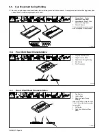
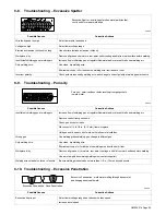
Page 36: ...nt Along Seam 3 Weave Patterns Use weave patterns to cover a wide area in one pass of the electrode S 0054 A 3 1 2 9 6 Poor Weld Bead Characteristics 1 Large Spatter Deposits 2 Rough Uneven Bead 3 Slight Crater During Welding 4 Bad Overlap 5 Poor Penetration 5 4 2 3 1 S 0053 A 9 7 Good Weld Bead Characteristics 1 Fine Spatter 2 Uniform Bead 3 Moderate Crater During Welding Weld a new bead or layer...

Page 37: ...s in weld metal S 0635 Possible Causes Corrective Actions Insufficient shielding gas at welding arc Increase flow of shielding gas at regulator flowmeter and or prevent drafts near welding arc Remove spatter from gun nozzle Check gas hoses for leaks Place nozzle 1 4 to 1 2 in 6 13 mm from workpiece Hold gun near bead at end of weld until molten metal solidifies Wrong gas Use welding grade shieldin...

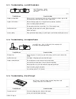
Page 38: ... welding power source 9 12 Troubleshooting Incomplete Fusion Incomplete Fusion failure of weld metal to fuse completely with base metal or a preceeding weld bead S 0637 Possible Causes Corrective Actions Workpiece dirty Remove all grease oil moisture rust paint undercoating and dirt from work surface before welding Insufficient heat input Select higher voltage range and or adjust wire feed speed I...

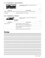
Page 39: ...port hand on solid surface or use two hands 9 15 Troubleshooting Distortion Distortion contraction of weld metal during welding that forces base metal to move Base metal moves in the direction of the weld bead S 0642 Possible Causes Corrective Actions Excessive heat input Use restraint clamp to hold base metal in position Make tack welds along joint before starting welding operation Select lower v...

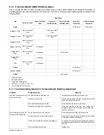
Page 40: ...e Pass Welding Only 4 90 HE 7 1 2 AR 2 1 2 CO2 5 Also for GMAW P All Positions 9 17 Troubleshooting Guide For Semiautomatic Welding Equipment Problem Probable Cause Remedy Wire feed motor operates but wire does not feed Too little pressure on wire feed rolls Increase pressure setting on wire feed rolls Incorrect wire feed rolls Check size stamped on wire feed rolls replace to match wire size and t...

Page 41: ...ating Have Factory Authorized Service Agent replace gas solenoid valve Incorrect primary voltage connected to welding power source Check primary voltage and relink welding power source for correct voltage Welding arc not stable Wire slipping in drive rolls Adjust pressure setting on wire feed rolls Replace worn drive rolls if necessary Wrong size gun liner or contact tip Match liner and contact ti...

Page 42: ... 087 299 10 per package 030 in 0 8 mm 770 177 5 per package 000 067 10 per package 035 in 0 9 mm 770 180 5 per package 000 068 10 per package 045 in 1 2 mm 770 183 5 per package 000 069 10 per package MIG Nozzle Standard 770 404 169 715 Gasless Flux Cored Nozzle 770 487 226 190 Tip Adapter 770 402 169 716 Replacement Liners 023 025 in 0 6 mm 196 139 194 010 030 035 in 0 8 0 9 mm 196 139 194 011 03...

Page 43: ...cturer Hobart s 5 3 1 Limited Warranty shall not apply to 1 Consumable components such as contact tips cutting nozzles contactors brushes relays work station table tops and welding curtains or parts that fail due to normal wear Exception brushes and relays are covered on all engine driven products 2 Items furnished by Hobart Miller but manufactured by others such as engines or trade accessories Th...

Page 44: ...hers Co 2013 01 Hobart Brothers Co An Illinois Tool Works Company 2200 Corporate Drive Troy OH 45373 USA For Assistance Call1 800 332 3281 Model Name Serial Style Number Purchase Date Date which equipment was delivered to original customer Distributor Address City State Zip Please complete and retain with your personal records Owner s Record Thank you for purchasing Hobart Our trained technical su...

Reviews: