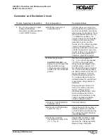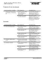
Protective Circuit
NOTE: The protective relays and protective monitor are not completely functional until the load contactor is
closed. Since it is not advisable to vary voltages for test purposes while delivering power to an
aircraft, the generator should be connected to a load bank for troubleshooting the protective circuits.
To avoid repetition, it will be assumed that the reset switch [(36), Fig. 1] has been pushed and the
load contactor has been closed before commencing each test.
Trouble, Symptom & Condition
Test or Inspection
Corrective Action
1.
Load contactor opens during
power delivery. Overvoltage
indicating light ON.
a. The over voltage condition
may have been the result of
a sudden drop in the load,
or possible tampering with
voltage regulator
adjustment potentiometer
(37, Fig. 1 ), and may have
been a normal action.
Use voltage adjusting rheostat
(37, Fig. 1) to reduce voltage to
110-V AC. Observe voltmeter
and gradually increase voltage
with rheostat. If the
over-under-voltage sensing
module (K26) functions to open
the load contactor at any value
less than 130-V AC, it is
defective. Replace
over-under-voltage module or
complete protection relay tray.
b. Defective protective monitor
module (K14).
If overvoltage light comes on at
110-V, unplug over-under
voltage module and close
contactor. If the Overvoltage
light comes on, the protective
monitor module (K14) is
defective.
NOTE: it is normal for the
undervoltage light to come on
during this test.
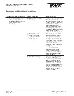
2.
Load contactor opens during
power delivery. Undervoltage
indicating light ON.
a. An undervoltage condition
caused the over-under-
voltage sensing module
(K26) to function normally.
Observe generator voltage on
voltmeter and adjust to normal
115-V AC with voltage regulator
adjustment potentiometer (37,
Fig. 1). Resume normal
operation. If the load contactor
opens again and an under-
voltage condition is indicated by
light (DS38) proceed to step B.
b. Defective over-under-
voltage module (K26).
Use voltage regulator
adjustment potentiometer(38,
Fig. 1) to reduce voltage to
104-V. Wait 12 seconds. The
undervoltage indicating light
should NOT be turned on. If the
light is turned on, the
undervoltage relay is defective.
Replace the module (K26) or
the protective relay tray.
OM-2040 / Operation and Maintenance Manual
90D20 / Generator Sets
Chapter 3-1
February 28/94 Revised
Page 22
Summary of Contents for 6921 Series
Page 2: ...This page intentionally left blank ...
Page 223: ......
Page 224: ......
Page 225: ......
Page 226: ......
Page 227: ......
Page 228: ......
Page 229: ......
Page 230: ......
Page 231: ......
Page 232: ......
Page 233: ......
Page 234: ......
Page 235: ......
Page 236: ......
Page 237: ......
Page 238: ......
Page 239: ......
Page 240: ......
Page 241: ......
Page 242: ......
Page 243: ......
Page 244: ......
Page 245: ......
Page 246: ......
Page 247: ......
Page 248: ......
Page 249: ......
Page 250: ......
Page 251: ......
Page 252: ......
Page 253: ......
Page 254: ......
Page 255: ......
Page 256: ......
Page 257: ......
Page 258: ......
Page 259: ......
Page 260: ......


