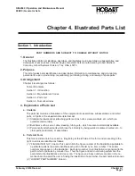
Section 3. Parts List
1. Explanation of Parts List Arrangement
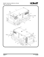
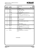
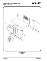
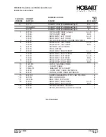
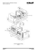
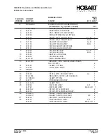
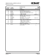
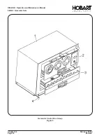
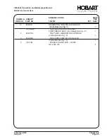
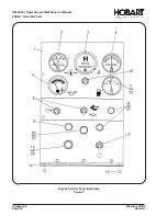
The parts list is arranged so that the illustration will appear on a lefthand page and the applicable parts
list will appear on the opposite righthand page. Unless the list is unusually long, the user will be able to
look at the illustration and read the parts list without turning a page.
2. Symbols and Abbreviations
The following is a list of symbols and abbreviations used in the parts list.
*
- item not illustrated
A, or AMP
- ampere
AC
- alternating current
AR
- as required
DC
- direct current
Fig.
- Figure
hd.
- head
hex
- hexagon
Hz
- Hertz (cycles-per-second)
I.D.
- inside diameter
IN
- inch
kVA
- kilovolt-ampere
uF
- microfarad
No.
- number
NHA
- next higher assembly
OM
- Owners Manual
PRV
- peak reverse voltage
PSI
- pounds per square inch
Ref
- reference (the item has been listed previously)
T-R
- transformer-rectifier
V
- volt (when used as a prefix to a five-digit number, indicates vendor code)
NOTE: An item which does not reflect an index number is an assembly which is not illustrated in its
assembled state, or it is similar (right-hand, left-hand, top, etc.) to an item which is illustrated.
OM-2040 / Operation and Maintenance Manual
90D20 / Generator Sets
February 28/94
Chapter 4-3
Revised
Page 1
Summary of Contents for 6921 Series
Page 2: ...This page intentionally left blank ...
Page 223: ......
Page 224: ......
Page 225: ......
Page 226: ......
Page 227: ......
Page 228: ......
Page 229: ......
Page 230: ......
Page 231: ......
Page 232: ......
Page 233: ......
Page 234: ......
Page 235: ......
Page 236: ......
Page 237: ......
Page 238: ......
Page 239: ......
Page 240: ......
Page 241: ......
Page 242: ......
Page 243: ......
Page 244: ......
Page 245: ......
Page 246: ......
Page 247: ......
Page 248: ......
Page 249: ......
Page 250: ......
Page 251: ......
Page 252: ......
Page 253: ......
Page 254: ......
Page 255: ......
Page 256: ......
Page 257: ......
Page 258: ......
Page 259: ......
Page 260: ......

