The solid-state circuitry is designed to close the relay contacts when output current in ANY
phase reaches 125% of normal, rated output capacity. The closed relay sends a signal to the
protective monitor. This signal “gates” the overload SCR
(silicon-controlled rectifier)
in the
protective monitor and interrupts the load contactor to open.
The following is a list of overload module characteristics:
NOTE: The overload protective system will function when any phase carries 123% to 127% of rated
current.
At 125% load the device will function in 5 minutes.
At 150% load the device will function in 16 seconds.
NOTE: All times are plus or minus 25% and are nonadjustable.
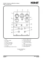
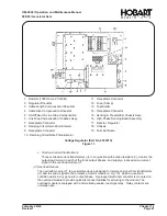
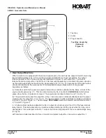
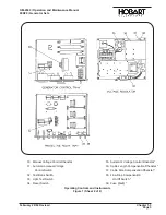
1. Overload Resistor (16.6 Ohm, 25 Watt
for 90-kva)
2. Terminal Board
3. Overload Current Transformer
4. Ammeter Current Transformer
5. Rectifier
6. Load Contactor
7. Overload Module
8. Line Drop Resistor (50 Ohm,
25 Watt)
9. Line Drop Current Transformer
10. Blocking Diode
Power Module Panel Assembly
Figue 14
OM-2040 / Operation and Maintenance Manual
90D20 / Generator Sets
Chapter 1-1
February 28/94
Page 22
Revised
Summary of Contents for 6921 Series
Page 2: ...This page intentionally left blank ...
Page 223: ......
Page 224: ......
Page 225: ......
Page 226: ......
Page 227: ......
Page 228: ......
Page 229: ......
Page 230: ......
Page 231: ......
Page 232: ......
Page 233: ......
Page 234: ......
Page 235: ......
Page 236: ......
Page 237: ......
Page 238: ......
Page 239: ......
Page 240: ......
Page 241: ......
Page 242: ......
Page 243: ......
Page 244: ......
Page 245: ......
Page 246: ......
Page 247: ......
Page 248: ......
Page 249: ......
Page 250: ......
Page 251: ......
Page 252: ......
Page 253: ......
Page 254: ......
Page 255: ......
Page 256: ......
Page 257: ......
Page 258: ......
Page 259: ......
Page 260: ......

