(4)
Rectifier
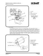
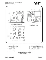
A diode-bridge rectifier
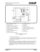
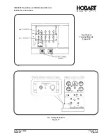
(5, Fig. 14)
receives 400-Hz AC from phase C of the generator output
and converts it to a pulsating, direct current for energization of the load contactor holding coil
only. This DC coil-holding circuit is controlled indirectly by the 400-Hz AC to the rectifier. The
ground circuit for the rectifier’s AC supply must pass through the relay contacts in the protective
monitor module to ground cable N. Therefore, any time a protective device functions to open the
protective monitor relay, the rectifier’s circuit is opened. No DC is then available for the load
contactor holding coil, hence, the load contactor opens.
6. Test Box
The test box is an optional accessory item used for testing the generator set. All generator sets are
wired to accommodate a test box, however, the box is supplied only when ordered.
(Part Number
388318A-2).
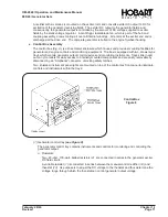
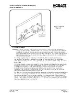
a. Description
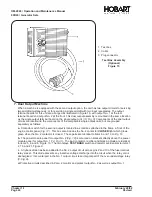
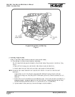
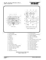
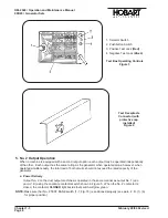
(See Fig. 15)
The test box assembly consists of a rotary selector switch, momentary contact pushbutton switch,
and two insulated-tip test jacks, mounted in a small metal box. Connection to the generator set is
made through a wiring harness equipped with a 26-contact plug connector which mates with a
receptacle connector.I
b. Theory of Operation
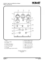
Wire leads are connected to the electrical circuitry of the generator set at various points and routed
to a receptacle connector mounted on the engine control panel. They are connected to the test box
rotary switch by a plug connector and wiring harness.
The rotary selector switch is wired in such a manner that for any switch position, two pre-selected
test points in the generator set circuitry are connected for testing.
The selector switch may be rotated to any one of 22 positions, however, not all positions are used in
this installation. An instruction plate mounted under the switch knob indicates switch positions and
component tested in each position. Normal voltage for each test is also indicated.
Two test jacks are provided for connection of the test prods of a voltmeter. After the voltmeter is
connected and selector switch positioned, the test circuit is closed by pressing the pushbutton
switch. A voltage value may then be observed on the voltmeter. This arrangement prevents
energization of test circuitry and equipment for extended periods and allows the operator to reset and
adjust the voltmeter without disconnecting it from the box.
For operating instructions, see Sect. 1-3, Para. 3.
OM-2040 / Operation and Maintenance Manual
90D20 / Generator Sets
February 28/94
Chapter 1-1
Revised
Page 23
Summary of Contents for 6921 Series
Page 2: ...This page intentionally left blank ...
Page 223: ......
Page 224: ......
Page 225: ......
Page 226: ......
Page 227: ......
Page 228: ......
Page 229: ......
Page 230: ......
Page 231: ......
Page 232: ......
Page 233: ......
Page 234: ......
Page 235: ......
Page 236: ......
Page 237: ......
Page 238: ......
Page 239: ......
Page 240: ......
Page 241: ......
Page 242: ......
Page 243: ......
Page 244: ......
Page 245: ......
Page 246: ......
Page 247: ......
Page 248: ......
Page 249: ......
Page 250: ......
Page 251: ......
Page 252: ......
Page 253: ......
Page 254: ......
Page 255: ......
Page 256: ......
Page 257: ......
Page 258: ......
Page 259: ......
Page 260: ......

