5. No. 2 Output Operation
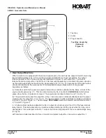
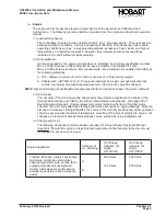
When a machine is equipped with a second output option, each output may be operated independently
of the other. Each output has the same rating as the generator when operated alone; however, when
operated simultaneously, the total load of both circuits should not exceed the rated capacity of the
generator.
a. Power Delivery
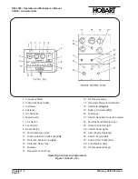
Output No. 2 on the dual output machines is operated in the same manner as output No. 1
(see
para. 2. E)
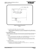
using the duplicate contactor switch shown in Figure 5. When the No. 2 contactor is
closed, the contactor CLOSED light beside that switch will glow green.
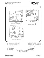
NOTE: Make sure that No. 2 TEST BANK switch (1-1; Fig. 18) is positioned properly (see para. 2. D. (1) (b)
for proper position).
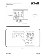
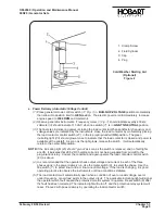
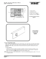
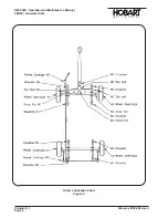
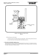
1. Selector Switch
2. Pushbutton Switch
3. Positive Test Jack
(Red)
4. Negative Test Jack
(Black)
Test Box Operating Controls
Figure 3
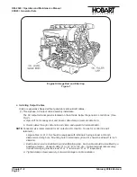
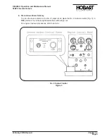
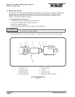
Test Receptacle
Connector (with
protective cap
installed)
Figure 4
OM-2040 / Operation and Maintenance Manual
90D20 / Generator Sets
Chapter 1-3
February 28/94 Revised
Page 8
Summary of Contents for 6921 Series
Page 2: ...This page intentionally left blank ...
Page 223: ......
Page 224: ......
Page 225: ......
Page 226: ......
Page 227: ......
Page 228: ......
Page 229: ......
Page 230: ......
Page 231: ......
Page 232: ......
Page 233: ......
Page 234: ......
Page 235: ......
Page 236: ......
Page 237: ......
Page 238: ......
Page 239: ......
Page 240: ......
Page 241: ......
Page 242: ......
Page 243: ......
Page 244: ......
Page 245: ......
Page 246: ......
Page 247: ......
Page 248: ......
Page 249: ......
Page 250: ......
Page 251: ......
Page 252: ......
Page 253: ......
Page 254: ......
Page 255: ......
Page 256: ......
Page 257: ......
Page 258: ......
Page 259: ......
Page 260: ......

