(2)
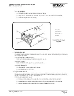
Tray installation
a. Use both hands to support tray as in removal above.
b. Align rails (4) with tracks (5) and slide tray into box. Latches will lock automatically.
c. Connect Amphenol Connector (3).
c. Generator Exciter
Provisions have been made to allow removal of the generator exciter without disturbing or removing
the complete generator.
(1)
Preparation for exciter removal.
Remove front access panel to remove generator exciter.
(2)
Exciter removal:
Refer to TM-360 in Chapter 6 for exciter instructions.
(3)
Exciter installation:
a. Install exciter in accordance with TM-360.
b. Reinstall front access panel.
d. Engine Control Panel
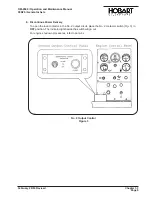
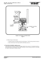
The engine control panel is designed and mounted so that it may be released and tilted outward for
access to components on the back side
(see Fig. 7)
.
(1)
Tilt out engine control panel
a. Remove clamp screw which supports wire conduit above output terminal panel.
b. Remove two cap screws which attach engine control panel to frame of control box.
c. Maneuver panel to tilt it inward at the bottom and outward at the top.
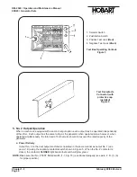
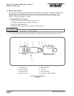
1. Latch
2. Fastener
3. Connector
4. Rail
Typical Tray Removal
Figure 8
OM-2040 / Operation and Maintenance Manual
90D20 / Generator Sets
February 28/94 Revised
Chapter 2-1
Page 11
Summary of Contents for 6921 Series
Page 2: ...This page intentionally left blank ...
Page 223: ......
Page 224: ......
Page 225: ......
Page 226: ......
Page 227: ......
Page 228: ......
Page 229: ......
Page 230: ......
Page 231: ......
Page 232: ......
Page 233: ......
Page 234: ......
Page 235: ......
Page 236: ......
Page 237: ......
Page 238: ......
Page 239: ......
Page 240: ......
Page 241: ......
Page 242: ......
Page 243: ......
Page 244: ......
Page 245: ......
Page 246: ......
Page 247: ......
Page 248: ......
Page 249: ......
Page 250: ......
Page 251: ......
Page 252: ......
Page 253: ......
Page 254: ......
Page 255: ......
Page 256: ......
Page 257: ......
Page 258: ......
Page 259: ......
Page 260: ......

