b. Flashing exciter field without test box.
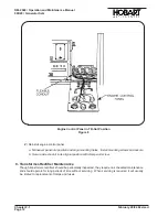
Remove test receptacle cover
(1-3; Fig. 3)
. Use two test leads equipped with a test prod on
one end and an “alligator” clip on the other. Insert the test prod of one lead in terminal “D” of
the test receptacle and momentarily touch the other end
(alligator clip)
to the “hot” terminal
(4, Fig. 4)
on the starter solenoid to flash the field.
Flashing the field in a reverse direction could cause damage to voltage regulator
diodes.
(11)
Check position of load contactor “on-off” switch
(21 Fig. 1)
, and generator control mode switch
(17)
.
a. Load contactor switch (21) must be in
OFF
position.
b. Generator mode control switch (17) must be in
IDLE
position.
CAUTION
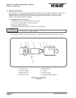
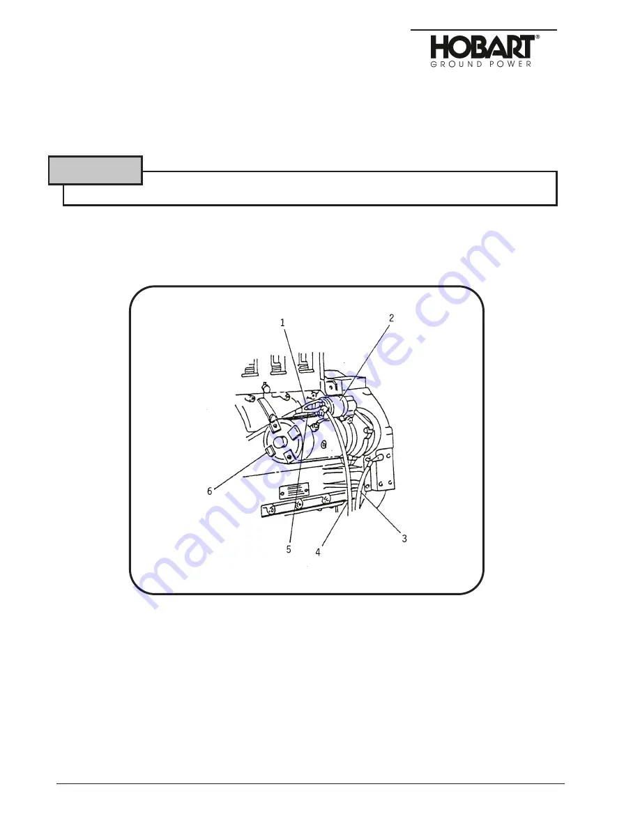
1. Starter Connection to Solenoid
2. Solenoid
3. Negative Battery Cable Connection
4. Positive Battery Cable
5. Starter Solenoid Switch
6. Starter
Starter and Solenoid Switch
Figure 2
OM-2040 / Operation and Maintenance Manual
90D20 / Generator Sets
Chapter 2-3
February 28/94 Revised
Page 4
Summary of Contents for 6921 Series
Page 2: ...This page intentionally left blank ...
Page 223: ......
Page 224: ......
Page 225: ......
Page 226: ......
Page 227: ......
Page 228: ......
Page 229: ......
Page 230: ......
Page 231: ......
Page 232: ......
Page 233: ......
Page 234: ......
Page 235: ......
Page 236: ......
Page 237: ......
Page 238: ......
Page 239: ......
Page 240: ......
Page 241: ......
Page 242: ......
Page 243: ......
Page 244: ......
Page 245: ......
Page 246: ......
Page 247: ......
Page 248: ......
Page 249: ......
Page 250: ......
Page 251: ......
Page 252: ......
Page 253: ......
Page 254: ......
Page 255: ......
Page 256: ......
Page 257: ......
Page 258: ......
Page 259: ......
Page 260: ......


