(12)
Check adjustable voltage range in automatic operating mode.
a. Observe voltmeter (3, Fig. 1) and turn rheostat (35)
CLOCKWISE
to full clockwise position.
Maximum voltage should be at least 134 V AC, or higher.
NOTE: If voltage should decrease when the knob is turned clockwise, it indicates that internal wiring of the
voltage regulator is incorrect. Replace the complete regulator tray assembly.
b. Observe voltmeter and turn rheostat knob to full
COUNTERCLOCKWISE
position. Minimum
voltage should be 108 V AC, or lower.
(13)
Observe voltmeter and adjust rheostat to obtain 115-V AC voltmeter reading.
(14)
Check adjustable voltage range in manual operating mode.
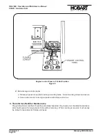
a. Open the generator control tray (15, Fig. 1) and place the automatic manual switch (31) in
MANUAL
position.
b. Observe voltmeter (3) and turn manual control rheostat (30) CLOCKWISE to full clockwise
position. Maximum voltage should be 160 V AC.
c. Observe voltmeter (3) and turn rheostat (30) to full
COUNTERCLOCKWISE
position.
Minimum voltage should be 95 V AC or less.
d. Adjust voltage to 115 V AC, then return automanual switch to
AUTOMATIC
position.
(15)
Position load bank switches, etc., to apply a light load to the generator.
(16)
Place the load contactor “on-off” switch
(21, Fig. 1)
in the top, spring loaded, CLOSE position.
Hold in this position momentarily. The indicating light
(23)
should glow GREEN and an
amperage value should appear on the DC ammeter
(19)
.
(17)
Release switch
(21)
and allow to return to center ON position. Load contactor should open
immediately, and generator “on” indicating light should go OFF. This indicates that the plug
interlock contacts are OPEN as they should be when the interlock coil is not receiving 28-V DC
power.
(18)
Open protective relay tray and place the test bank switch
(32, Fig. 1)
in TEST BANK position.
(19)
Again place load contactor switch
(21)
in the top, CLOSE position. Light
(23)
should glow
GREEN and remain ON when the switch is released and allowed to return to the center ON
position. This indicates that the test bank switch
(32)
is functioning to by-pass the plug interlock
relay.
(20)
Return the test bank switch to AIRCRAFT position. The load contactor should open at once and
the green indicating light
(23)
should go off.
(21)
Connect a source of 24-V DC power
(two 12-volt batteries connected in series)
to terminals “N”
and “F”
(or “E”)
at the output terminal panel. Polarity connection should be: MINUS to terminal
N and PLUS to terminal E or F.
(22)
With test-bank switch in AIRCRAFT position, hold the contactor operating switch
(21)
in top,
CLOSE position momentarily. The generator “ON” indicating light
(23)
should glow GREEN and
remain ON when the switch is released and allowed to return to the center ON position. This
indicates that the load contactor is closed and the plug interlock relay is functioning properly.
(23)
Apply 1/3 to 1/2 load at the load bank and allow the unit to run for 15 to 30 minutes. Observe
operation of all monitoring instruments.
(24)
Increase load bank resistance to apply a full load.
(25)
Check operation of the governor by observing the frequency meter
(1, Fig. 1)
when generator is
switched from no-load to full-load and vice versa frequency drop should be no more than 1 Hz.
Adjust governor as necessary
[(see Para. 4, E, (3)]
.
(26)
Follow instructions in Para. 4, B, (2), (b) to set voltage regulator line-drop compensation
potentiometers
[(Ref. Figure 1, items (36) and (37)]
. Set knob pointer on cable size
potentiometer (37) to size
(2/0, 4/0, etc.)
of cable being used. Set knob pointer on cable length
potentiometer (36) to length (20 feet, 40 feet, etc.) of cable being used. See instruction plate
(mounted below knobs).
OM-2040 / Operation and Maintenance Manual
90D20 / Generator Sets
Chapter 2-3
February 28/94 Revised
Page 6
Summary of Contents for 6921 Series
Page 2: ...This page intentionally left blank ...
Page 223: ......
Page 224: ......
Page 225: ......
Page 226: ......
Page 227: ......
Page 228: ......
Page 229: ......
Page 230: ......
Page 231: ......
Page 232: ......
Page 233: ......
Page 234: ......
Page 235: ......
Page 236: ......
Page 237: ......
Page 238: ......
Page 239: ......
Page 240: ......
Page 241: ......
Page 242: ......
Page 243: ......
Page 244: ......
Page 245: ......
Page 246: ......
Page 247: ......
Page 248: ......
Page 249: ......
Page 250: ......
Page 251: ......
Page 252: ......
Page 253: ......
Page 254: ......
Page 255: ......
Page 256: ......
Page 257: ......
Page 258: ......
Page 259: ......
Page 260: ......

