(27)
Check voltage regulator, at intervals, from no-load to full load, and on up to 125% load. Observe
and note voltage at various loads. Voltages should vary no more than plus or minus 1% from
115 V.
(28)
Check accuracy of voltmeter.
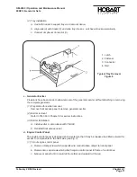
a. Open generator control tray (15, Fig. 1).
b. Connect a master voltmeter of known accuracy to terminals of the voltmeter (3).
c. Compare unit voltmeter reading with master meter. Error must not exceed 4% of full scale.
(29)
Check accuracy of AC ammeter.
a. Connect a master ammeter of known accuracy to the AC ammeter (4) terminals.
b. Compare unit ammeter reading with master meter under various loads. Error must not
exceed 4% of full scale.
(30)
Check operation of meter selector switch
(6)
. A voltage value should be shown in each switch
position.
(31)
Check operation of the line switch
(7)
. A normal voltage of 115 V AC should be indicated when
the switch is in LINE-TO-NEUTRAL position. A voltage of approximately 200 V AC should be
indicated when the switch is placed in LINE-TO-LINE position.
(32)
Check accuracy of frequency meter.
a. Connect an accurate master frequency meter to the frequency meter (1) terminals.
b. Compare meter readings. Error must not exceed 1% of full scale.
(33)
Operate the unit for a full 10 minutes under full load. The overload device
(Ref. 1-1; 7, Fig. 13)
MUST NOT trip.
(34)
Operate at 125% rated load for 5 minutes immediately following the full-load run. The overload
device MUST trip within 5 minutes and the overload indicating light
(10, Fig. 9)
must come ON
to indicate an overload condition.
(35)
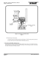
Reduce load to normal. Turn off indicating light by pressing reset switch
(7, Fig. 9).
(36)
Check engine oil pressure and oil temperature at rated operating speed
(2000 RPM)
. Oil
pressure gage should indicate at least 38 PSI when the engine is hot. Oil temperature gage
should indicate 190 F
(88 C)
5 F
(3 C)
when engine is hot.
(37)
Check operation of fuse interlock
(Ref. 1-1; 2, Fig. 9)
. With unit operating normally under load,
remove protective relay circuit fuse
(Ref. 17, Fig. 9)
. The load contactor should open
immediately. This indicates that the fuse interlock relay is functioning properly. Replace fuse
and apply load.
NOTE :Perform all protective relay tests with the unit operating under load.
(38)
Check operation of overvoltage relay and indicating light.
a. With the unit operating at normal load, adjust the voltage regulator rheostat (37, Fig. 1) to
increase voltage (clockwise), until the overvoltage sensing relay activates the protective
monitor. This will open the load contactor and turn on the overvoltage indicating light. The
overvoltage sensing relay should trip when voltage reaches 130V to 134V.
OM-2040 / Operation and Maintenance Manual
90D20 / Generator Sets
February 28/94 Revised
Chapter 2-3
Page 7
Summary of Contents for 6921 Series
Page 2: ...This page intentionally left blank ...
Page 223: ......
Page 224: ......
Page 225: ......
Page 226: ......
Page 227: ......
Page 228: ......
Page 229: ......
Page 230: ......
Page 231: ......
Page 232: ......
Page 233: ......
Page 234: ......
Page 235: ......
Page 236: ......
Page 237: ......
Page 238: ......
Page 239: ......
Page 240: ......
Page 241: ......
Page 242: ......
Page 243: ......
Page 244: ......
Page 245: ......
Page 246: ......
Page 247: ......
Page 248: ......
Page 249: ......
Page 250: ......
Page 251: ......
Page 252: ......
Page 253: ......
Page 254: ......
Page 255: ......
Page 256: ......
Page 257: ......
Page 258: ......
Page 259: ......
Page 260: ......


