OM-928 Page 19
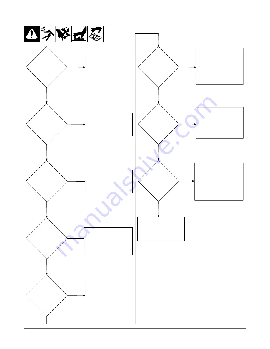
6-5. Troubleshooting Power Source
Connect unit to proper input
voltage. (see Section 4-7).
Yes
No
Is input power
connected to
correct line
voltage?
Is Power
switch in the
On position?
Place Power switch in the
On position. (see Section
5-1).
No
Yes
Is the cooling
fan running?
Check Power switch S1,
relay CR2, and thermistor
R1.
No
Yes
Is Power light
On?
Reset Power switch S1 and
verify line power voltage.
Check relay CR2, thermistor
R1, and Control board PC1.
No
Yes
Is Trouble
light On?
Check torch consumables.
Reset Power switch S1. If
unit is overheated, wait
while fan cools down unit
temperature.
No
Yes
Momentarily press torch
trigger and listen for gas/air
valve operation. Check for
Postflow air at torch. Check
Control board PC1, air filter,
and gas/air connections to
PC1 and torch.
Yes
No
Is compressor
operating?
Press torch trigger and
check if pilot arc ignites.
Check torch consumables.
*Check torch connections,
relay CR1, gas/air system,
and torch.
Yes
No
Does pilot arc
ignite?
Place torch near workpiece
and check if pilot arc “jumps”
or transfers to workpiece.
Check work clamp connec-
tion. *Check Control board
PC1 and connections, and
torch and its connections.
Yes
No
Does pilot arc
transfer to
workpiece?
Check all connections,
Check main transformer T1,
Check inductor L1. Return
to beginning of chart.
*Servicing procedure to be performed
only by authorized Service Station.
*
*
*
Summary of Contents for AirForce 250A
Page 4: ......
Page 25: ...OM 928 Page 21 SECTION 7 ELECTRICAL DIAGRAM 213 899 A Figure 7 1 Circuit Diagram ...
Page 29: ...Notes ...
Page 30: ...Notes ...


