background image

OM-923 Page 5

SECTION 2 

 CONSIGNES DE SÉCURITÉ 

 LIRE AVANT UTILISATION

fre_som _3/05

Y

Avertissement : se protéger et protéger les autres contre le risque de blessure — lire et respecter ces consignes.
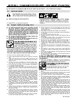
2-1.

Symboles utilisés

Symbole graphique d’avertissement ! Attention ! Cette pro-

cédure comporte des risques possibles ! Les dangers éven-

tuels sont représentés par les symboles graphiques joints.

Y

Indique un message de sécurité particulier

.

Signifie NOTE ; n’est pas relatif à la sécurité.

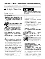
Ce groupe de symboles signifie Avertissement ! Attention ! Risques

d’ÉLECTROCUTION, ORGANES MOBILES et PARTIES

CHAUDES. Consulter les symboles et les instructions afférentes 

ci-dessous concernant les mesures à prendre pour supprimer

les dangers.

2-2.

Dangers relatifs au soudage à l’arc

Y

Les symboles représentés ci-dessous sont utilisés dans ce manuel

pour attirer l’attention et identifier les dangers possibles. En

présence de l’un de ces symboles, prendre garde et suivre les

instructions afférentes pour éviter tout risque. Les instructions en

matière de sécurité indiquées ci-dessous ne constituent qu’un

sommaire des instructions de sécurité plus complètes fournies

dans les normes de sécurité énumérées dans la Section 2-5. Lire et

observer toutes les normes de sécurité.

Y

Seul un personnel qualifié est autorisé à installer, faire fonction-

ner, entretenir et réparer cet appareil.

Y

Pendant le fonctionnement, maintenir à distance toutes les per-

sonnes, notamment les enfants de l’appareil.

UNE DÉCHARGE ÉLECTRIQUE peut

entraîner la mort.

Le contact d’organes électriques sous tension peut

provoquer des accidents mortels ou des brûlures

graves. Le circuit de l’électrode et de la pièce est

sous tension lorsque le courant est délivré à la

sortie. Le circuit d’alimentation et les circuits internes de la machine

sont également sous tension lorsque l’alimentation est sur Marche.

Dans le mode de soudage avec du fil, le fil, le dérouleur, le bloc de

commande du rouleau et toutes les parties métalliques en contact

avec le fil sont sous tension électrique. Un équipement installé ou mis

à la terre de manière incorrecte ou impropre constitue un danger.

D

Ne pas toucher aux pièces électriques sous tension.

D

Porter des gants isolants et des vêtements de protection secs et sans

trous.

D

S’isoler de la pièce à couper et du sol en utilisant des housses ou des

tapis assez grands afin d’éviter tout contact physique avec la pièce à

couper ou le sol.

D

Ne pas se servir de source électrique à courant électrique dans les zo-

nes humides, dans les endroits confinés ou là où on risque de tomber.

D

Se servir d’une source électrique à courant électrique UNIQUEMENT si

le procédé de soudage le demande.

D

Si l’utilisation d’une source électrique à courant électrique s’avère né-

cessaire, se servir de la fonction de télécommande si l’appareil en est

équipé.

D

D’autres consignes de sécurité sont nécessaires dans les conditions

suivantes : risques électriques dans un environnement humide ou si l’on

porte des vêtements mouillés ; sur des structures métalliques telles que

sols, grilles ou échafaudages ; en position coincée comme assise, à ge-

noux ou couchée ; ou s’il y a un risque élevé de contact inévitable ou

accidentel avec la pièce à souder ou le sol. Dans ces conditions, utiliser

les équipements suivants, dans l’ordre indiqué : 1) un poste à souder DC

à tension constante (à fil), 2) un poste à souder DC manuel (électrode)

ou 3) un poste à souder AC à tension à vide réduite. Dans la plupart des

situations, l’utilisation d’un poste à souder DC à fil à tension constante

est recommandée. En outre, ne pas travailler seul !

D

Couper l’alimentation ou arrêter le moteur avant de procéder

à l’installation, à la réparation ou à l’entretien de l’appareil. Déverrouiller

l’alimentation selon la norme OSHA 29 CFR 1910.147 (voir normes de

sécurité).

D

Installer le poste correctement et le mettre à la terre convenablement

selon les consignes du manuel de l’opérateur et les normes nationales,

provinciales et locales.

D

Toujours vérifier la terre du cordon d’alimentation. Vérifier et s’assurer

que le fil de terre du cordon d’alimentation est bien raccordé à la borne

de terre du sectionneur ou que la fiche du cordon est raccordée à une

prise correctement mise à la terre.

D

En effectuant les raccordements d’entrée, fixer d’abord le conducteur

de mise à la terre approprié et contre-vérifier les connexions.

D

Vérifier fréquemment le cordon d’alimentation afin de s’assurer qu’il

n’est pas altéré ou à nu, le remplacer immédiatement s’il l’est. Un fil à nu

peut entraîner la mort.

D

L’équipement doit être hors tension lorsqu’il n’est pas utilisé.

D

Ne pas utiliser des câbles usés, endommagés, de grosseur insuffisante

ou mal épissés.

D

Ne pas enrouler les câbles autour du corps.

D

Si la pièce soudée doit être mise à la terre, le faire directement avec un

câble distinct.

D

Ne pas toucher l’électrode quand on est en contact avec la pièce, la terre

ou une électrode provenant d’une autre machine.

D

Ne pas toucher des porte électrodes connectés à deux machines en

même temps à cause de la présence d’une tension à vide doublée.

D

N’utiliser qu’un matériel en bon état. Réparer ou remplacer sur-le-

champ les pièces endommagées. Entretenir l’appareil conformément à

ce manuel.

D

Porter un harnais de sécurité si l’on doit travailler au-dessus du sol.

D

S’assurer que tous les panneaux et couvercles sont correctement en

place.

D

Fixer le câble de retour de façon à obtenir un bon contact métal-métal

avec la pièce à souder ou la table de travail, le plus près possible de la

soudure.

D

Isoler la pince de masse quand pas mis à la pièce pour éviter le contact

avec tout objet métallique.

D

Ne pas raccorder plus d’une électrode ou plus d’un câble de masse à

une même borne de sortie de soudage.

Il reste une TENSION DC NON NÉGLIGEABLE dans

les sources de soudage onduleur quand on a coupé

l’alimentation.

D

Arrêter les convertisseurs, débrancher le courant électrique et

décharger les condensateurs d’alimentation selon les instructions indi-

quées dans la partie Entretien avant de toucher les pièces.

Le soudage génère des fumées et des gaz. Leur

inhalation peut être dangereuse pour la santé.

LES FUMÉES ET LES GAZ peuvent

être dangereux.

D

Ne pas mettre sa tête au-dessus des vapeurs. Ne pas respirer ces va-

peurs.

D

À l’intérieur, ventiler la zone et/ou utiliser une ventilation forcée au niveau de

l’arc pour l’évacuation des fumées et des gaz de soudage.

D

Si la ventilation est médiocre, porter un respirateur anti-vapeurs approu-

vé.

D

Lire et comprendre les spécifications de sécurité des matériaux (MSDS) et

les instructions du fabricant concernant les métaux, les consommables, les

revêtements, les nettoyants et les dégraisseurs.

D

Travailler dans un espace fermé seulement s’il est bien ventilé ou en

portant un respirateur à alimentation d’air. Demander toujours à un sur-

veillant dûment formé de se tenir à proximité. Des fumées et des gaz de

soudage peuvent déplacer l’air et abaisser le niveau d’oxygène provo-

quant des blessures ou des accidents mortels. S’assurer que l’air de

respiration ne présente aucun danger.

D

Ne pas souder dans des endroits situés à proximité d’opérations de dé-

graissage, de nettoyage ou de pulvérisation. La chaleur et les rayons de

l’arc peuvent réagir en présence de vapeurs et former des gaz haute-

ment toxiques et irritants.

D

Ne pas souder des métaux munis d’un revêtement, tels que l’acier gal-

vanisé, plaqué en plomb ou au cadmium à moins que le revêtement n’ait

été enlevé dans la zone de soudure, que l’endroit soit bien ventilé et en

portant un respirateur à alimentation d’air. Les revêtements et tous les

métaux renfermant ces éléments peuvent dégager des fumées toxi-

ques en cas de soudage.

Summary of Contents for H-9B

Page 1: ...OM 923 223 112C 2006 08 Processes Arc Welding Power Source And Wire Feeder Description Flux Cored FCAW Welding Handler 125 EZ And H 9B Gun R File Flux Cored FCAW ...

Page 2: ...ducts Please take time to read the Safety precautions They will help you protect yourself against potential hazards on the worksite We ve made installation and operation quick and easy With Hobart you can count on years of reliable service with proper maintenance And if for some reason the unit needs repair there s a Troubleshooting section that will help you figure out what the problem is The par...

Page 3: ...on EMF 8 SECTION 3 SPECIFICATIONS 9 3 1 Specifications 9 3 2 Duty Cycle And Overheating 9 3 3 Volt Ampere Curves 10 SECTION 4 INSTALLATION 11 4 1 Installing Work Clamp 11 4 2 Process Polarity Table 11 4 3 Polarity 11 4 4 Installing Wire Spool And Adjusting Hub Tension 12 4 5 Selecting A Location And Connecting Input Power For 115 VAC Model 13 4 6 Installing Contact Tip And Nozzle 14 4 7 Threading ...

Page 4: ...haracteristics 30 8 7 Good Weld Bead Characteristics 30 8 8 Troubleshooting Excessive Spatter 31 8 9 Troubleshooting Porosity 31 8 10 Troubleshooting Excessive Penetration 31 8 11 Troubleshooting Lack Of Penetration 32 8 12 Troubleshooting Incomplete Fusion 32 8 13 Troubleshooting Burn Through 32 8 14 Troubleshooting Waviness Of Bead 33 8 15 Troubleshooting Distortion 33 8 16 Troubleshooting Guide...

Page 5: ... 147 see Safety Standards D Properly install and ground this equipment according to its Owner s Manual and national state and local codes D Always verify the supply ground check and be sure that input power cord ground wire is properly connected to ground terminal in disconnect box or that cord plug is connected to a properly grounded receptacle outlet D When making input connections attach proper...

Page 6: ...bustibles such as a butane lighter or matches from your person before doing any welding D Follow requirements in OSHA 1910 252 a 2 iv and NFPA 51B for hot work and have a fire watcher and extinguisher nearby FLYING METAL can injure eyes D Welding chipping wire brushing and grinding cause sparks and flying metal As welds cool they can throw off slag D Wear approved safety glasses with side shields ...

Page 7: ... computers and communicationsequipment D Have only qualified persons familiar with electronic equipment perform this installation D The user is responsible for having a qualified electrician prompt ly correct any interference problem resulting from the installa tion D If notified by the FCC about interference stop using the equipmentat once D Have the installation regularly checked and maintained ...

Page 8: ...Occupational Safety and Health Standards for General Indus try Title 29 Code of Federal Regulations CFR Part 1910 Subpart Q and Part 1926 Subpart J from U S Government Printing Office Super intendent of Documents P O Box 371954 Pittsburgh PA 15250 there are 10 Regional Offices phone for Region 5 Chicago is 312 353 2220 website www osha gov 1 6 EMF Information Considerations About Welding And The E...

Page 9: ...n selon la norme OSHA 29 CFR 1910 147 voir normes de sécurité D Installer le poste correctement et le mettre à la terre convenablement selon les consignes du manuel de l opérateur et les normes nationales provinciales et locales D Toujours vérifier la terre du cordon d alimentation Vérifier et s assurer que le fil de terre du cordon d alimentation est bien raccordé à la borne de terre du sectionne...

Page 10: ...e de ses poches telles qu un allumeur au butane ou des allumettes D Suivre les consignes de OSHA 1910 252 a 2 iv et de NFPA 51B pour travaux de soudage et prévoir un détecteur d incendie et un ex tincteur à proximité DES PARTICULES VOLANTES peuvent blesser les yeux D Le soudage l écaillement le passage de la pièce à la brosse en fil de fer et le meulage génèrent des étincelles et des particules mé...

Page 11: ...interférences avec les équipe ments de radio navigation et de communica tion les services de sécurité et les ordinateurs D Demander seulement à des personnes qualifiées familiarisées avec des équipements électroniques de faire fonctionner l instal lation D L utilisateurest tenu de faire corriger rapidement par un électri cien qualifié les interférences résultant de l installation D Si le FCC signa...

Page 12: ...art 1926 Subpart J de U S Government Printing Office Superinten dent of Documents P O Box 371954 Pittsburgh PA 15250 il y a 10 bureaux régionaux le téléphone de la région 5 Chicago est 312 353 2220 site Internet www osha gov 2 6 Information EMF Considérations sur le soudage et les effets de basse fréquence et des champs magnétiques et électriques Le courant de soudage pendant son passage dans les ...

Page 13: ...a 030 035 in 0 8 0 9 mm 183 295 IPM 4 6 7 5 m min At No Load 112 236 IPM 2 8 6 0 m min Feeding Wire CSA Rating 3 2 Duty Cycle And Overheating Duty Cycle is percentage of 10 min utes that unit can weld at rated load without overheating If unit overheats thermostat s opens output stops and cooling fan runs Wait fifteen minutes for unit to cool Reduce amperage or duty cycle before welding Y Exceeding...

Page 14: ...e output capabilities of the welding power source Curves of other settings fall between the curves shown ssb1 1 10 91 210 519 A 8 0 13 0 18 0 23 0 28 0 33 0 0 0 10 0 20 0 30 0 40 0 50 0 60 0 70 0 80 0 90 0 100 0 110 0 120 0 130 0 Range1 Range2 Range3 Range4 Amperage Voltage 18 16 ga 16 12 ga 12 10 ga 10ga 3 16 ...

Page 15: ...en hardware A loose electrical connection will cause poor weld performance and excessive heating of the work clamp 7 16 in 4 2 Process Polarity Table Process Polarity Cable Connections Process Polarity Cable To Gun Cable To Work Clamp FCAW Self shielding wire no shielding gas DCEN Straight Polarity Connect to negative output terminal Connect to positive output terminal 4 3 Polarity Polarity must b...

Page 16: ...802 971 C 803 012 803 013 B Installing 8 in 203 mm Wire Spool Installing 4 in 102 mm Wire Spool When a slight force is needed to turn spool tension is set Retaining ring used with 8 in 203 mm spool only Adapter used with 8 in 203 mm spool only Only applies to units equipped with optional hub kit Overtightening hub tension may cause wire feed problems ...

Page 17: ...ted by time de lay fuses or circuit breaker is re quired 3 Plug From Unit Select extension cord of 14 AWG for up to 50 ft 15 m or 12 AWG for 50 up to 200 ft 61 m Y Special installation may be required where gasoline or volatile liquids are present see NEC Article 511 or CEC Section 20 804 122 C Y Do not move or operate unit where it could tip 18 in 460 mm 18 in 460 mm 1 2 3 ...

Page 18: ...3 Flux Nozzle MIG Nozzle Use with flux cored wire only Narrow design allows access in tight spaces and provides better visibility of puddle during welding Use with solid or flux cored wire Push nozzle over contact tip and adapter until it is seated onto adapter Contact tip will be exposed approximately 7 16 in 11 3 mm when installed properly Push nozzle over contact tip and adapter until it is sea...

Page 19: ... Cut off wire Close door Press gun trigger until wire comes out of gun Turn power on INPUT POWER 6 in 150 mm Tighten Loosen knob completely then rotate pressure adjustment knob in a clockwise direction until drive roll is tight against the welding wire Adjust drive roll pressure just tightly enough to prevent wire from slipping against drive roll during operation Tighten Be sure that wire is posit...

Page 20: ...5 OPERATION 5 1 Controls 1 Material Thickness Selector Switch Use switch to select the material thickness range Do not switch under load Switch must click into detent position for weld output 2 Power Switch Ref 230 001 A 1 2 ...

Page 21: ...OM 923 Page 17 5 2 Operating The Gun Ref 804 240 A 1 Trigger Switch When pressed energized wire feeds 1 ...

Page 22: ...or vacuum inside During heavy service clean monthly Or 6 2 Overload Protection 804 127 A 1 SupplementaryProtector CB1 CB1 protects unit from overload If CB1 opens unit shuts down Reset supplementary protector 1 6 3 Drive Motor Protection Drive motor protection circuit protects drive motor from overload If drive motor becomes inoperative release gun trigger and wait until protection circuit resets ...

Page 23: ...uching Reinstall plate and tighten screws 7 Retaining Knob Rotate counterclockwise and remove knob 8 Drive Roll The drive roll consists of two different sized grooves Each side is stamped with the proper size Select the groove that matches the wire size on the wire spool Install drive roll onto motor shaft so that correct groove size stamp faces out away from drive housing 9 Retaining Knob Opening...

Page 24: ...ct Tip Tools Needed Ref 804 241 A Y Turn off welding power source 1 Nozzle Remove nozzle 2 Contact Tip 3 Tip Adapter Cut off welding wire at contact tip Remove contact tip from tip adapter and install new contact tip Reinstall nozzle 1 2 3 ...

Page 25: ...blow out liner Remove nozzle Cut off wire at contact tip and remove contact tip and tip adapter Thread wire according to Section 4 7 Reassemble drive cover and gun in reverse order from taking it apart Open pressure assembly Retract wire from liner onto spool Hold wire tightly to keep it from unraveling Secure end of wire at spool Remove screws 3 from cover and remove cover from wire drive assembl...

Page 26: ...cable and top ring forward over head tube Separate gun handle halves Loosen liner setscrew Loosen and remove retaining nut from liner Pull liner out of gun cable If necessary twist cable to ease removal Y Turn off welding power source Install retaining nut on one end of liner Lay gun cable straight on a flat surface Insert bare end of liner end without retaining nut into wire drive end of cable Pu...

Page 27: ... liner after cutting to length 3 8 in 10 mm Reassemble gun by placing head tube and cable into one half of handle Be sure trigger is properly installed into trigger slot Thread welding wire through gun see Section 4 7 Reinstall adapter contact tip and nozzle Reinstall cover onto wire drive assembly and secure with screws 3 Insert retaining nut into adapter and adjust liner stickout as shown Tighte...

Page 28: ...ine fuse or reset circuit breaker if open Place Power switch in On position see Section 5 1 Reset welding power source supplementary protector if open No weld output wire does not feed fan motor continues to run Thermostat TP1 open overheating Allow fan to run with gun trigger switch off thermostat resets when unit has cooled see Section 3 2 Be sure that Material Thickness Selector switch is not s...

Page 29: ...OM 923 Page 25 SECTION 7 ELECTRICAL DIAGRAM 230 951 A Figure 7 1 Circuit Diagram ...

Page 30: ...nnections Y Weld current can damage electronic parts in vehicles Disconnect both battery cables before welding on a vehicle Place work clamp as close to the weld as possible Wire Feeder Power Source Workpiece Gun Work Clamp fcaw 1 2003 Ref 803 444 A Self ShieldingFlux Core Wire ...

Page 31: ... 035 in Recommendation Wire Speed Approx 1 8 or 0 125 in 0 001 in 1 ampere 0 125 in 125 A Wire Size Amperage Range 0 023 in 0 030 in 0 035 in Select Wire Size Wire Size 0 023 in 0 030 in 0 035 in 3 5 in per ampere 2 in per ampere 1 6 in per ampere Select Wire Speed Amperage 125 A based on 1 8 in material thickness ipm inches per minute Low voltage wire stubs into work High voltage arc is unstable ...

Page 32: ...mm past end of nozzle and tip of wire is positioned correctly on seam NOTE 1 Hold Gun and Control Gun Trigger 2 Workpiece 3 Work Clamp 4 Electrode Extension Stickout 1 4 to 1 2 in 6 To 13 mm 5 Cradle Gun and Rest Hand on Workpiece 2 3 5 4 90 90 0 15 45 45 1 0 15 S 0421 A End View of Work Angle Side View of Gun Angle GROOVE WELDS End View of Work Angle Side View of Gun Angle FILLET WELDS Drag ...

Page 33: ... voltage NOTE Slow FILLET WELD ELECTODE EXTENSIONS STICKOUT ELECTRODE EXTENSIONS STICKOUT GUN ANGLES AND WELD BEAD PROFILES 10 10 GUN TRAVEL SPEED S 0634 Push Perpendicular Drag or Pull Short Normal Long Short Normal Long Normal Fast Electrode directed ahead of bead Electrode pointed back into bead Direction Of Welding The Drag or Pull technique is generally recommended when welding with flux core...

Page 34: ...ent Along Seam 3 Weave Patterns Use weave patterns to cover a wide area in one pass of the electrode S 0054 A 3 1 2 8 6 Poor Weld Bead Characteristics 1 Large Spatter Deposits 2 Rough Uneven Bead 3 Slight Crater During Welding 4 Bad Overlap 5 Poor Penetration 5 4 2 3 1 S 0053 A 8 7 Good Weld Bead Characteristics 1 Fine Spatter 2 Uniform Bead 3 Moderate Crater During Welding Weld a new bead or laye...

Page 35: ...s resulting from gas pockets in weld metal S 0635 Possible Causes Corrective Actions Wrong gas Use welding grade shielding gas change to different gas Dirty welding wire Use clean dry welding wire Eliminate pick up of oil or lubricant on welding wire from feeder or liner Workpiece dirty Remove all grease oil moisture rust paint coatings and dirt from work surface before welding Use a more highly d...

Page 36: ...omplete Fusion failure of weld metal to fuse completely with base metal or a preceeding weld bead S 0637 Possible Causes Corrective Actions Workpiece dirty Remove all grease oil moisture rust paint undercoating and dirt from work surface before welding Insufficient heat input Set Metal Thickness Selector switch to a higher selection Improper welding technique Place stringer bead in proper location...

Page 37: ...correct wire feed rolls Check size stamped on wire feed rolls replace to match wire size and type if necessary Wire spool brake pressure too high Decrease brake pressure on wire spool Restriction in the gun and or assembly Check and replace cable gun tip adapter and contact tip if damaged Check size of contact tip and cable liner replace if necessary Wire curling up in front of the wire feed rolls...

Page 38: ...34 SECTION 9 PARTS LIST Hardware is common and not available unless listed 804 124 B 1 2 3 4 5 6 6 7 8 9 10 11 12 13 14 15 16 17 18 19 36 20 21 22 23 24 25 26 27 30 28 29 31 32 33 34 35 37 Figure 8 1 Main Assembly ...

Page 39: ...868 STABILIZER 1 20 196 575 SWITCH rocker spst 1 21 229 432 SWITCH rotary 1 22 207 079 KNOB pointer 1 23 210 398 BUSHING snap in 1 24 209 412 BUSHING snap in 500 dia 2 25 209 532 DRIVE assy wire 1 26 193 144 INSULATOR output stud 1 27 202 726 ADAPTER spool hub 1 28 202 998 SPRING cprsn 1 29 204 608 NUT 1 30 203 072 WASHER 1 31 225 397 H 9B GUN 8 ft 023 035 1 32 223 790 LABEL setup guide 1 33 204 0...

Page 40: ...1 125 6 226 010 NUT liner retainer 1 7 226 080 HANDLE ASSY 1 OPTIONAL To maintain the factory original performance of your equipment use only Manufacturer s Suggested Replacement Parts Model and serial number required when ordering parts from your local distributor Table 8 1 Contact Tip Options HOBART PART NO DESCRIPTION REMARKS 196 131 Tip contact scr 030 wire Pkg of 5 196 132 Tip contact scr 035...

Page 41: ... 8 212 388 CUP spring 1 9 212 389 SCREW torch cover 1 To maintain the factory original performance of your equipment use only Manufacturer s Suggested Replacement Parts Model and serial number required when ordering parts from your local distributor Table 8 2 Options PART NO DESCRIPTION REMARKS 194 776 Small Running Gear Cylinder Rack To Mount Unit For Maneuverability 195 216 Hub Kit For 8 in Wire...

Page 42: ...Notes ...

Page 43: ...ntact tips cutting nozzles slip rings drive rolls gas diffusers plasma torch tips and electrodes weld cables and tongs and tips or parts that fail due to normal wear Exception brushes slip rings and relays are covered on Hobart Engine Driven models 2 Items furnished by Hobart Miller but manufactured by others such as engines or trade accessories These items are covered by the manufacturer s warran...

Page 44: ...or service location Call 1 877 Hobart1 or visit our website at www HobartWelders com Contact your Distributor for Welding Supplies and Consumables Options and Accessories Personal Safety Equipment Service and Repair Replacement Parts Training Schools Videos Books Technical Manuals Servicing Information and Parts Circuit Diagrams Welding Process Handbooks Contact the Delivering Carrier to Resources...

Reviews: