


OM-240 362 Page 11
SECTION 7
−
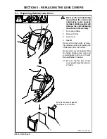
INSTALLING OPTIONAL MAGNIFYING LENS
1
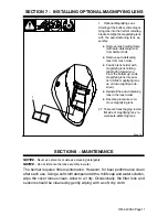
Optional Magnifying Lens
Starting at the bottom, slide magni-
fying lens into the helmet retaining
brackets. Align the magnifying lens
with the auto-darkening lens as-
sembly.
D
Remove lens holding frame
(with auto-darkening lens)
from helmet shell.
D
Remove auto-darkening
lens from lens holder.
D
Position lens holder with
magnifying lens holding
tabs facing toward you.
From the bottom up, slide
magnifying lens into posi-
tion. (Slide magnifying lens
up or down slightly as de-
sired.)
D
Reinstall the auto-darkening
lens in the lens holder.
D
Reverse procedure to re-
move magnifying lens.
.
To prevent lens fogging, install
flat side of magnifying lens to-
ward auto-darkening lens.
804 818
1
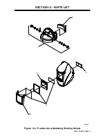
SECTION 8
−
MAINTENANCE
NOTICE
−
Never use solvents or abrasive cleaning detergents.
NOTICE
−
Do not immerse the lens assembly in water.
The helmet requires little maintenance. However, for best performance clean
after each use. Using a soft cloth dampened with a mild soap and water solution,
wipe the cover lenses clean. Allow to air dry. Occasionally, the filter lens and
sensors should be cleaned by gently wiping with a soft, dry cloth.


