29
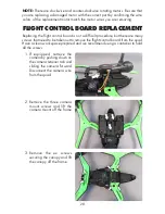
4.
There are four screws holding
each motor cover to the frame.
Remove all four motor covers
from the frame. The motors
should come out with the
covers. Disconnect the motors
and set the covers aside. We
recommend labelling each
cover so they are installed
back in the correct locations.
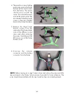
5.
Remove the three frame
bottom covers from the
underside of the frame. Make
note of the different screw
sizes used when removing
the covers. Carefully push the
LED lenses out of the frame
bottom covers.
6.
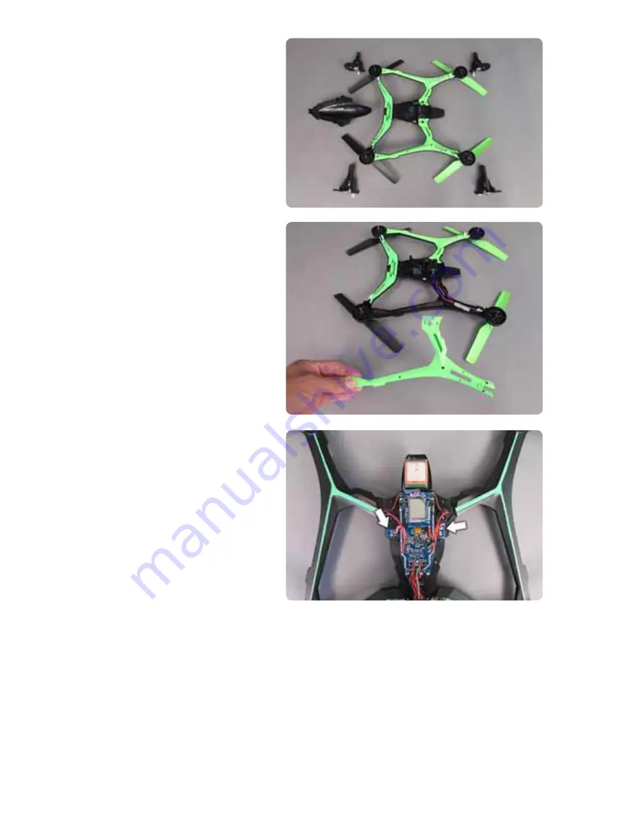
Uns c rew t he camera
connector and the battery
connector from the frame.
NOTE:
Before moving on to step 7, take a close look at how the wires and LEDs
are positioned in the frame. Take a picture if possible for future reference. The
wires should be reinstalled with the new board as they are currently placed.


