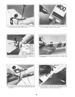
(11) Next, make a 90° bend downwards at the mark and cut-off the excess so that
there is only 5/16" of rod after the bend.
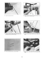
(1) Epoxy the small mounting brace to the top of the firewall Fill any gap with
epoxy.
(12) Attach the rods to the servos using the rod clevises as shown in the above
drawing. You may need to enlarge the holes.
(2) Trim away some of the plastic from under the front of the fuselage where
shown.
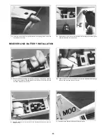
COWL AND PROP INSTALLATION
(A) Cowl . . . . . . . . . . . . . . . . . . . . . . . . . . . . . . . . . . . . . . .1
(B) Cowl Brace . . . . . . . . . . . . . . . . . . . . . . . . . . . . . . . . . . . .1
(C) 3mmx8mm Self Tapping Screw . . . . . . . . . . . . . . . . . . . . . . . . .3
(D) Spinner . . . . . . . . . . . . . . . . . . . . . . . . . . . . . . . . . .1
(E) Spinner Back Plate . . . . . . . . . . . . . . . . . . . . . . . . . . . . . . . .1
(F) 3mmx 12mm Self Tapping Screw . . . . . . . . . . . . . . . . . . . . . . . . .2
(in spinner)
(G) Mounting Block . . . . . . . . . . . . . . . . . . . . . . . . . . . . . . . . .1
(3) Epoxy the cowl brace onto the front of the fuselage. Make sure that the beveled
ends angle down in line with the fuselage. Connect fuel lines.
-23-


