background image

is correct, the model should continue along the same flight
path for at least a dozen plane lengths before gravity
starts to naturally bring it down.

Do each maneuver several times, to make sure that

you are getting a proper diagnosis. Often, a gust, an
accidental nudge on the controls, or just a poor
maneuver entry can mislead you. The thrust adjustments
are a real pain to make. On most models, it means taking
the engine out, adding shims, then reassembling the
whole thing. Don’t take shortcuts.

Don’t try to proceed with the other adjustments until

you have the thrust line and/or C.G. correct. They are the
basis upon which all other trim settings are made.

Also, while you have landed, take the time to crank

the clevises until the transmitter trims are at neutral.
Don’t leave the airplane so that the transmitter has some
odd-ball combination of trim settings. One bump of the
transmitter and you have lost everything. The trim must
be repeatable, and the only sure way to do this is to
always start with the transmitter control trims at the
middle.

The next maneuver is somewhat more tricky than it

looks. To verify C.G., we roll the model up to a 45° bank,
then take our hands off the controls. The model should
go a reasonable distance with the fuse at an even keel.
If the nose pitches down, remove some nose weight, and
the opposite if the nose pitches up. The trick is to use
only the ailerons to get the model up at a 45° bank. We
almost automatically start feeding in elevator, but that’s a
no-no. Do the bank in both directions, just to make sure
that you are getting an accurate reading of the
longitudinal balance.

We now want to test the correct alignment of both

sides of the elevator (even if they aren’t split, like a
Pattern ship’s, they can still be warped or twisted). Yaw
and lateral balance will also come into play here, so be
patient and eliminate the variables, one-by-one. The
maneuver is a simple loop, but it must be entered with
the wings perfectly level. Position the maneuver so that
your assistant can observe it end-on. Always loop into
the wind. Do several loops, and see if the same symptom
persists. Note if the model loses heading on the front or
back side of the loop. If you lose it on the way up, it’s
probably an aileron problem, while a loss of heading on
the way back down is most likely a rudder situation.

Note that the Yaw test is the same looping

sequences. Here, however, we are altering rudder and
ailerons, instead of the elevator halves. We must repeat
that many airplanes just will not achieve adequate lateral
trim without sealing the hinge gaps shut. The larger you
make the loops (to a point), the more discernable the
errors will be.

The Lateral Balance test has us pulling those loops

very tightly. Pull straight up into a vertical and watch
which wing drops. A true vertical is hard to do, so make
sure that your assistant is observing from another
vantage point. Note that the engine torque will affect the

vertical fall off, as will rudder errors. Even though we
balance the wing statically before leaving for the field, we
are now trimming it dynamically.

The Aileron Coupling (or rigging), is also tested by

doing Hammerheads Stalls. This time, however, we want
to observe the side view of the model. Does the plane
want to tuck under a bit? If so, then try trimming the
ailerons down a small bit, so that they will act as flaps. If
the model tends to want to go over into a loop, then rig
both ailerons up a few turns on the clevises. Note that
drooping the ailerons will tend to cancel any washout
you have in the wing. On some models, the lack of
washout can lead to some nasty characteristics at low
speeds.

Again, we reiterate that all of these controls are

interactive. When you change the wing incidence, it will
influence the way the elevator trim is at a given C.G. Re-
trimming the wing will also change the rigging on the
ailerons, in effect, and they may have to be readjusted
accordingly.

The whole process isn’t hard. As a matter of fact it’s

rather fun – but very time consuming. It’s amazing what
you will learn about why a plane flies the way it does, and
you’ll be a better pilot for it. One thing we almost
guarantee, is that your planes will be more reliable and
predictable when they are properly trimmed out. They
will fly more efficiently, and be less prone to doing radical
and surprising things. Your contest scores should
improve, too.

We wish to acknowledge the Orlando, Florida, club
newsletter, from which the basics of the chart presented
here were gleaned.

Reprinted in part by Great Planes Model Manufacturing
Company, courtesy of Scale R/C Modeler magazine, Pat
Potega, Editor, August 1983 issue.

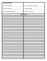
See the Flight Trimming Chart on Page 23

22

Summary of Contents for Hobbistar 60 MKII

Page 1: ...as quickly as possible 1 ALWAYS return your entire system including airplane and radio 2 Disconnect the receiver battery switch harness and make sure that the transmitter is turned off Disconnect all...

Page 2: ...ow to Purchase Missing pieces Contact Hobby Services see warranty front page Plans Construction Plans Plans are not available for ARF models Manual Instructions Contact Hobby Services see warranty fro...

Page 3: ...ng Joiner 12 Aileron Servo Tray 13 Plywood Servo Tray 14 Engine Mount Straps 15 Aileron Servo Tray Blocks 16 Wing Joining Tape 17 Pushrods and Pushrod Tubes 14 17 Clothespins Epoxy Brushes GPMR8062 Mi...

Page 4: ...the location of the throttle servo and throttle pushrod exit on the firewall so plan ahead Radio Equipment In selecting a radio system for your Hobbistar 60 MKII you ll need at least a 4 channel radi...

Page 5: ...ns Before you fly 1 Make sure that no other fliers are using your radio frequency 2 Your radio transmitter must be the FIRST thing you turn ON and the LAST thing you turn OFF 3 Double check all contro...

Page 6: ...eral amount of 30 minute epoxy to the joiner and the wing ribs Put the wing joiner into the joiner box in the wing and push the two wing halves together and allow the glue to cure 4 Use masking tape t...

Page 7: ...to accommodate most servos If it is not deep enough for your particular brand of servos glue the servo tray to the two 1 4 6mm balsa blocks included in the kit and then glue the blocks to the wing wi...

Page 8: ...the fuselage Do not glue it in place 6 Apply a piece of masking tape across the top of the fuselage at the back of the wing saddle Mark the center of the fuselage on the tape Insert a T pin on the cen...

Page 9: ...r in relation to the wing The distance from the top of the stab to the bottom of the wing should be the same If each end of the stabilizer is not equal in distance from the wing lightly sand one side...

Page 10: ...selage bottom The hole needs to be drilled at a 30 angle Cut one of the white tubes to 11 and rough it up with 240 grit sandpaper Insert the tube into the fuselage so that the end of the tube is even...

Page 11: ...m screws All three wheels should turn freely If not trim the inside of the wheel slightly 1 Locate the two metal engine mount straps 2 Put your engine onto the engine mount Note Depending on your engi...

Page 12: ...ssembly into the fuel tank and tighten the stopper screw 7 Install the tank into the fuel tank compartment Apply a bead of silicone sealant around the fuel tank cap when installing the tank into the f...

Page 13: ...here the holes need to be drilled Note When installing the control horns the centerline of the control horn holes must be the same as the center line of the hinge joint as shown in the above sketch Dr...

Page 14: ...included with your radio system 5 Plug the switch into the receiver and the receiver battery Plug the servos into the receiver consult your radio instruction manual for proper installation if you are...

Page 15: ...on the transmitter and receiver Set the throttle to full open Install the pushrod into the other screw lock pushrod connector then open the carburetor on your engine to full open Connect the throttle...

Page 16: ...recommended by the engine manufacturer along with the spinner By moving the position of the clevis at the control horn toward the outermost hole you will decrease the amount of throw of the control su...

Page 17: ...anced will be unstable and possibly unflyable 1 The balance point C G is located 3 1 2 89mm back from the leading edge of the wing Balance your Hobbistar 60 using a Great Planes C G Machine Airplane B...

Page 18: ...ing servo horn screws clevises servo cords and extensions Follow the battery charging procedures in your radio instruction manual You should always charge your transmitter and receiver batteries the n...

Page 19: ...ed room or garage Get help from an experienced pilot when learning to operate engines Use safety glasses when starting or running engines Do not run the engine in an area of loose gravel or sand the p...

Page 20: ...vator stick on your radio Maintain a gentle climbing attitude until the plane is approximately 75 feet high then begin a turn away from the pit area Once airborne you will find that the plane is a ver...

Page 21: ...model is statically trimmed It s only a starting point so don t be surprised if you wind up changing it all One other critical feature is that the ailerons must have their hinge gap sealed If shoving...

Page 22: ...on problem while a loss of heading on the way back down is most likely a rudder situation Note that the Yaw test is the same looping sequences Here however we are altering rudder and ailerons instead...

Page 23: ...de loops D Yaws right on insides and left on outside loops E Yaws left in insides and right on outside loops A Wings are level and plane falls to either side randomly B Falls off to left in loops Wors...

Page 24: ...d Date __________________ Where Purchased ___________________ Date Construction Started _____________ Date Construction Finished __________ Finished Weight ____________________ Date of First Flight __...

Reviews: