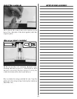
Attach the pushrods
❏
65. Attach the two clevises to the control horns.
Use the 2nd hole from the outside. Check to make
certain that the pushrods do not bind in the openings
and that they operate smoothly. Slide the clevis
retainer over the clevis forks.
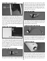
Center the servos with your radio
❏
66. Turn on the transmitter and then the receiver
switch. Center all of the trim levers and place the
throttle stick at its midway position. Turn off the
receiver switch and then the transmitter. By doing
this, your servos will be at their centered (neutral)
position when you connect the pushrods. Refer to the
following photos and replace or trim the servo arms as
shown. To do this, simply remove the servo arms and
reposition them on the splined servo output shaft.
Be
sure to reinstall the screws.
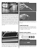
Mark the pushrods
❏
67. Holding the elevator in its neutral position,
mark the pushrod wire where it crosses the servo arm
as shown. Next, hold the rudder at its neutral position
and mark the wire the same way.
Cut the pushrods
❏
68. Cut off the pushrods approximately 3/8” past
the marks.
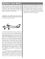
Connect the pushrods
❏
69. Make a “Z” bend at each mark. Remove the
servo arms from the servos. Attach the rods to the
servo arms. You may need to enlarge the holes slightly
on the arms. A 5/64” drill bit works great for this.
Reattach the servo arms in the same position.
Attach the pushrod connector
❏
70. Remove the servo arm and install a pushrod
connector on the opposite side of the rudder pushrod.
This will be for the steering rod. Thread the nut onto
the connector. The connector must be able to rotate
in the servo arm, so do not over–tighten the nut. Place
a drop of thin CA onto the threads to lock the nut in
23


