background image

There is one thing that you will need to fly your

SuperStar 60 safely that is not furnished with the kit:
You will need a 

qualified

instructor to teach you to fly.

No trainer ever made will let you teach yourself to fly
safely. It can be done, but you would be seriously
risking more than just the model. To find an
instructor, you should join an R/C flying club. If there
is not a club nearby, then you should find an
experienced model pilot who is willing to help you.
The chosen instructor should fly well enough to allow
you to concentrate on your own flying. If you are
worried about your instructor crashing your model,
you will not be able to concentrate on learning to fly.
After you have found an instructor, you should spend
some time just 

talking 

with him about what you will

be trying to learn. He should inspect the model to be
certain that it is ready to fly. Listen to him and try to
gain by his experience.

Now that you have a good model and an

instructor whom you trust, you can go out and get
started learning to fly. You can expect to be very
nervous at first, and you will make some mistakes.
There will be several instances where the instructor
will prevent you from crashing. This will be unsettling,
but the thing to do is jump right back into flying the
model (after your knees stop shaking, of course). This
is one of the most important things about learning to
fly model airplanes...

you have to fly!

Fly as often as

you can. Be sure to make several flights each time you
go to the flying field, but give yourself time after each
flight to calm down and discuss the flight with your
instructor. Spending some time after each flight
talking about what happened and what you need to
work on to improve your skills will pay off with greater
confidence in your own growing abilities.

CHARGE THE BATTERIES

Follow the battery charging procedures in your radio
instruction manual. You should 

always

charge your

transmitter and receiver batteries the night before you
go flying, and at other times as recommended by the
radio manufacturer.

FIND A SAFE PLACE TO FLY

1.

The best place to fly your R/C model is an AMA

(Academy of Model Aeronautics) chartered club field.
Ask your hobby shop dealer if there is such a club in

your area and join. Club fields are set up for R/C flying
which makes your outing safer and more enjoyable.
The AMA can also tell you the name of a club in your
area. We recommend that you join the AMA and a
local club so you can have a safe place to fly and also
have insurance to cover you in case of a flying
accident. (The AMA address is listed at the front of
this instruction book).

If there is not a flying club in your area, you need

to find a large area, free of obstructions, with a
smooth surface that can be used as a runway, and
located at least 6 miles away from any other R/C
airplane operation and away from houses, buildings
and streets. A schoolyard may look inviting but it is
too close to people, power lines and possible radio
interference.

GROUND CHECK THE MODEL

If you are not thoroughly familiar with the operation
of R/C models, ask an experienced modeler to check
to see that you have the radio installed correctly and
that all the control surfaces do what they are
supposed to. The engine operation must also be
checked and the engine “broken in” on the ground by
running the engine for at least two tanks of fuel.

Follow the engine manufacturer’s recommendations
for break-in.

Check to make sure all screws remain

tight, that the hinges are secure and that the prop is
on tight.

RANGE CHECK YOUR RADIO

Check the operation of the radio before every

time you fly. This means that with the transmitter
antenna collapsed and the receiver and transmitter
on, you should be able to walk at least 100 feet away
from the model and still have control. Have someone
help you. Have them stand by your model and, while
you work the controls, tell you what the various
control surfaces are doing.

Repeat this test 

with the engine running

at

various speeds with an assistant holding the model. If
the control surfaces are not acting correctly at all
times, 

do not fly!

Find and correct the problem first.

28

Preparing To Fly Your SUPERSTAR 60

Summary of Contents for Superstar 60

Page 1: ...Easy as 1 2 3 Entire Contents Copyright 2001 HCAZ3090 V 1 1 ...

Page 2: ...u want in your new hobby HCAA3070 Wing Kit HCAA3071 Fuselage Kit HCAA3072 Tail Set HCAA3073 Landing Gear Set 2 Landing Gear Part Quantity 10 Main landing gear wires 2 11 Nose gear wire 1 27 Nose gear control horn 1 29 Landing gear straps 2 31 Wheels 2 32 Wheel collars w set screws 4 47 3mm x 10mm wood screws 4 Wing Assembly Part Quantity 1 Right wing with aileron 1 2 Left wing with aileron 1 7 Ply...

Page 3: ...Part Quantity 12 Fuel tank 1 13 Tank stopper 1 14 Fuel pick up weight 1 15 Plastic stopper compression disks one large and one small 2 16 Aluminum fuel tubing one short and two long 3 17 3mm x 18mm self tapping screw 1 18 Silicone fuel line 1 33 Foam collar 1 3 8 40 51 16 14 18 17 13 15 50 43 44 33 19 45 43 35 32 11 51 15 25 26 50 24 47 23 29 10 9 1 6 136 12 2 6 6 6 9 13 14 18 16 33 17 28 3 52 29 ...

Page 4: ...ity 60 size model engine The O S 60 FP or SuperTigre S 61K are fine engines for this plane Look for fea tures such as easy break in easy starting efficient carburetion and low maintenance Check the manufacturer s recommendations for propellers to use with your engine Radio Equipment To let you send the commands that control your SuperStar s flight path you ll need a 4 channel air craft radio syste...

Page 5: ...e and radio 2 Disconnect the receiver battery switch harness and make sure that the transmitter is turned off Disconnect all batteries and drain all fuel 3 Include a list of all items returned and a THOROUGH written explana tion of the problem and service needed If you expect the repair to be covered under warranty also include your proof of purchase 4 Include your full return address and a phone ...

Page 6: ...ad steps 2 through 4 before gluing 2 Mix approximately 1 4oz 7 5ml of 6 minute epoxy Using a mixing stick or epoxy brush apply an even coat of epoxy on both sides of one of the wing joiners Sandwich this coated joiner between the remaining two Quickly proceed through the following steps 3 and 4 before the glue cures Remove the excess epoxy 3 Excess epoxy will squeeze out of the seams between the j...

Page 7: ...cator line will serve as a guide when cutting out the aileron servo hole Trial fit the wing joiner 8 Trial fit the wing joiner in both wings by sliding the joiner into the joiner cavity in the wing The joiner should slide in with little resistance up to the centerline Trial fit the wing halves together The two panels should fit flush with no gaps Sand the joiner 9 If the wing joiner will not fit i...

Page 8: ...test seam possible No gaps should be showing between the two wing halves Clean the excess epoxy from the outside of the wing using a paper towel dampened with rubbing alcohol Tape the wing halves together 14 Hold the wing halves in alignment while the epoxy is curing Use several strips of masking tape on both sides to hold the wing halves tightly together Let the glue cure Cut the aileron servo ho...

Page 9: ... is installed Assemble the servo tray 18 Glue the balsa aileron servo blocks onto the servo tray so that the angled side you just cut is facing away from the plywood tray Trial fitting the aileron servo 19 Trial fit the aileron servo into the servo tray and the hole cut in the bottom side of the wing Enlarge either hole if needed with a hobby knife or a fine toothed file until a proper fit is achi...

Page 10: ...onto each hinge Use a paper towel to absorb the excess glue Wait a few minutes for the glue to harden then flex the surface the other direction and glue the other side of the hinges Finally flex the back and forth several times to free up the aileron Install the aileron control horns 23 Thread the white aileron control horns onto the torque rods until there is 3 4 19mm of torque rod between the wi...

Page 11: ...eron pushrods installed 26 Locate the 1 4 6 5mm diameter clear retaining tube and cut two 1 4 6 5mm pieces Slide one piece on each of the two clevises to secure the connection between the clevis and the horn This concludes the wing assembly for now Tape the pushrods to the wing to keep them in place until you install the servo NOTES ON WING ASSEMBLY ...

Page 12: ...rubber bands will be used to hold the wing in place Locate the stab slot 3 Locate the horizontal stabilizer slot under the covering on the tail section of the fuselage by pressing lightly with your finger The slot will be located on both sides of the tail Using a hobby knife carefully remove the covering exposing the slots NOTE Do not cut into the wood around the slot Install the plywood stabilize...

Page 13: ... flex the surface all the way one direction DO NOT REMOVE THE SURFACE Apply 5 drops of thin CA onto each hinge Use a paper towel to absorb the excess glue Wait for a few minutes for the glue to harden then flex the surface the other direction and glue the other side of the hinges Finally flex the surface back and forth several times to free it up Mark the centerline 9 Locate the horizontal stabili...

Page 14: ...l of 30 minute epoxy Using a mixing stick place glue inside the horizontal stabilizer slot on all sides including the horizontal stabilizer mount Insert the stabilizer from the rear and adjust the alignment Wipe off any epoxy that squeezes out using a paper towel dampened with rubbing alcohol Set the fuselage aside until the glue cures Install the vertical fin 15 Trial fit the fin into the slot in...

Page 15: ...nto the control horn back plate on the opposite side of the rudder Tighten the screws but do not crush the balsa Cut off the excess threads that stick out using a wire cutter Install the elevator horn 19 Attach the elevator control horn in the same manner as the rudder Place the control horn on the bottom side of the elevator 1 1 8 28mm away from the fuselage side see previous photo at earlier ste...

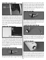
Page 16: ...age Using a hobby knife remove the covering from this channel Prepare the channel for the gear 23 Trial fit the wire landing gear struts into the holes If they will not go in easily drill out the two holes using a 13 64 drill bit Next bevel the inside corners of the holes so that the bend in the wire will seat fully into the holes Install the landing gear struts 24 Position the two wire struts in ...

Page 17: ...nside edge of the fuselage side Install the steering guide tube 30 Slide the remaining guide tube into the hole you just drilled so that 1 2 protrudes Mix up 1 8oz of 6 minute epoxy Glue the tube into the hole and into the lower left slot inside the fuselage Once the glue has cured trim off this tube so it is flush with the firewall Do not trim off the throttle tube Make Z bends on the wire 31 Mak...

Page 18: ...aluminum tube through the black rubber stopper The third aluminum tube will not be used Place the two white plastic discs over the tubes The larger disc should go towards the outside The nub on the small disc should face away from the rubber stopper Insert the 3 x 18mm self tapping screw through the larger disc rubber plug and then into the smaller disc Do not tighten the screw at this time Bend t...

Page 19: ... set the engine onto the mount Adjust the rails until they fit close to the engine case Remove the engine and tighten the four screws to secure the mount to the firewall Align the engine with the fuselage 44 Position the engine on the mount so that the face of the engine thrust washer is 1 4 forward of the fuselage sides Align the engine so that the crankshaft is pointing straight forward Mark the...

Page 20: ...51 Ream out the spinner backplate to fit on the engine Install the spinner backplate prop prop washer and the prop nut onto the engine Position the prop so it is horizontal when the engine is against its compression the point at which you feel resistance when you turn the crankshaft counter clockwise This is a good habit to get into when installing props onto model airplanes If the engine quits du...

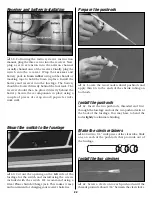
Page 21: ... You may need to sand the edges and corners slightly for a good fit Glue in place using thick CA Install the servos in the fuselage 57 Routing the wire servo leads forward install the servos into the tray using the screws included with the radio system Do not over tighten the screws They should only be snug Anything tighter will crush the grommets and allow the normal vibrations from the engine to...

Page 22: ... the fuselage 60 Cut out the opening on the left side of the fuselage for the switch and install using the screws included with the switch We recommend using a Great Planes Switch Charge jack This makes it easy and convenient for charging your receiver batteries Prepare the pushrods 61 Locate the two wooden dowel pushrods and apply thin CA to the ends of the shrink tubing on both rods Install the ...

Page 23: ...o output shaft Be sure to reinstall the screws Mark the pushrods 67 Holding the elevator in its neutral position mark the pushrod wire where it crosses the servo arm as shown Next hold the rudder at its neutral position and mark the wire the same way Cut the pushrods 68 Cut off the pushrods approximately 3 8 past the marks Connect the pushrods 69 Make a Z bend at each mark Remove the servo arms fr...

Page 24: ...ositioned off center to cause the aileron to travel further up than down which is known as differential aileron throw This will give smoother banking control and will reduce the airplanes adverse yaw tendency typical with flat bottom wings Make a Z bend at the mark on each wire and connect to the servo wheel You will have to remove the wheel to connect the rods Enlarge the holes if needed using a ...

Page 25: ...aller center hole along with the two remaining small wheel collars The wheels must all spin freely and have no tendency to bind Attach the Wing 77 Connect the aileron servo to the aileron extension and attach the wing onto the fuselage using 12 64 rubber bands Install 5 on each side first Then criss cross the remaining 2 This will hold the wing securely but will allow it to pop off in the event of...

Page 26: ...es full With the throttle set up properly you should be able to start and run the engine with the trim lever set midway to full position adjusted for a smooth but slow idle Then when it is time to stop the engine simply pull back the trim to close the carburetor and the engine will stop running 3 Check the movement of the control surfaces Use a ruler to match our measurements listed below If your ...

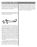
Page 27: ...g the balance forward may improve the smoothness and arrow like tracking but it may then require more speed for takeoff and make it more difficult to slow down for landing Moving the balance aft makes the model more agile with a lighter and snappier feel In any case please start at the location we recommend and do not at any time balance your model outside of the recommended range of 3 5 8 to 4 1 ...

Page 28: ... and at other times as recommended by the radio manufacturer FIND A SAFE PLACE TO FLY 1 The best place to fly your R C model is an AMA Academy of Model Aeronautics chartered club field Ask your hobby shop dealer if there is such a club in your area and join Club fields are set up for R C flying which makes your outing safer and more enjoyable The AMA can also tell you the name of a club in your ar...

Page 29: ...ne Do not put anything into the prop of a running engine AMA SAFETY CODE Read and abide by the Academy of Model Aeronautics Official Safety Code a portion of which is reprinted here GENERAL 1 I will not fly my model aircraft in sanctioned events air shows or model flying demonstrations until it has been proven to be airworthy by having been previously successfully flight tested 2 I will not fly my...

Page 30: ...r to take your time Follow your instructor s advice and learn to control the model in the many basic maneuvers possible with this model Landing When it s time to land do a couple of slow flybys again straight into the wind at a safe altitude and get familiar with the plane s slow flying characteristics Landings will involve learning to judge the height position direction and speed of the model in ...

Page 31: ...ed into it to monitor battery voltage during a flying session It is advisable to mount the charge jack in an accessible area of the fuselage so an ESV can be used without removing the wing Charger Device used to recharge batteries and is usual ly supplied with the radio if NiCd batteries are included Chicken Stick A hand held stick used to flip start a model airplane engine Clunk A weighted fuel p...

Page 32: ...urfaces on a standard type airplane located at the trailing edge of the wing which function as ailerons by moving differentially and as flaps by moving up or down together Flaperons require either a mechanical or electronic channel mixer Note Flaperons are an advanced feature and are not recommended on trainer aircraft Flight Box A special box used to hold and transport all equip ment used at the ...

Page 33: ...led by the elevator Pitch is illustrated by holding the air plane at each wingtip Raising or lowering the nose is the pitch movement This is how the climb or dive is controlled Pushrod A rigid piece of wood fiberglass nylon or steel used to transfer movement from a servo to a control surface or throttle Pylon Racing Airplane A model airplane designed for racing They are flown around a set course o...

Page 34: ...ode III Left hand stick con trols throttle and aileron Right hand stick controls elevator and rudder Single Stick A special trans mitter with only one stick Elevator and aileron are con trolled with the stick Rudder is controlled by twisting the end of the stick Throttle is con trolled by a lever on the top or side of the transmitter Note Single stick equipment is no longer being produced by most ...

Page 35: ...BUILDING NOTES Kit Purchase Date Date Construction Finished Where Purchased Finished Weight Date Construction Started Date of First Flight Flight Log 35 ...

Page 36: ... HCAP0100 RC Multi Charger HCAP0210 Power Core Charger HCAP0300 Deluxe Power Panel HCAP0351 ExpandedScaleVoltmeterMKII HCAP0356 Digital Voltmeter MKII HCAP0900 Power Core Starter Pack HCAQ2030 64 Rubber Bands 1 lb HCAP2175 Exhaust Deflector 35 90 HCAP2200 Recoil Fuel Tubing HCAQ1000 Latex Foam Rubber 1 4 HCAQ1050 Latex Foam Rubber 1 2 HCAR0311 1 Hobby Blades 100 pcs GPMR6002 Pro CA Glue Thin 1 oz ...

Reviews: