background image

                                                                                                  Last updated: 08/13/20108      Rev. 9 

16 


Note, you can see both limit switches from the back view.  

The Z-limit wires can now be moved directly up (in relation to the picture) and through the notch in the 
rear plate and inserted into the Z-Axis screw terminals.  


Summary of Contents for R7

Page 1: ...e very outdated they should only be used for reference We also advise finding a large clean flat surface to build your kit The first few steps can certainly be performed on a smaller surface however as the build grows you will need a four foot by four foot area flat surface It is also advised that you lay out each step individually with all parts for the respective step Lastly before starting the ...

Page 2: ...t the machine Z gantry plate limit faces down All wired NO Step One In the first step you will be assembling the Y gantry plates These plates will run on the side of the R7 as you are facing the machine One notable change from the videos is the 2mm shims are no longer needed At the end of this step you will have two assembled Y gantry plates each with eight mini wheels and three large wheels all o...

Page 3: ... STEP 1 Qty Smw3D Builder Y Gantry Plate LH 1 Y Gantry Plate RH 1 Large Xtreme Wheels 6 Mini Delrin Wheels 16 Adjustable Tension Anti Backlash Nut 2 6mm Spacers 8 6mm Mini Eccentric Spacers 14 3mm Spacers 4 M5x20 Bolt 4 M5x25 Bolt 22 ...

Page 4: ...it Begin by installing the standard spacers on the smaller holes bottom row these will be a reference for the rest of the wheels Tighten these with a small amount of torque do not tighten so much that the wheel drags or locks Next install the next row up eccentric spacers and mini wheels Before tightening turn the eccentrics until the wheel on this bolt is as close to the reference wheel below it ...

Page 5: ...ible to collapse the block Simply snug up and use lock tight You can adjust the tension on the ACME block at this time if you so choose Insert one of the ACME threaded rods into the block and adjust the set screw until there is slight resistance while trying to turn the ACME rod through the block Do not overdo it You can always adjust this after the build is complete ...

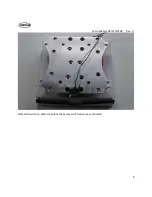
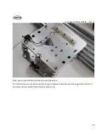
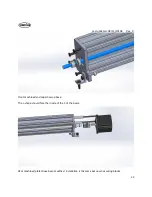
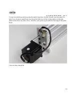
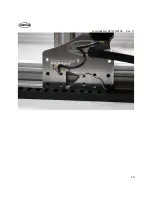
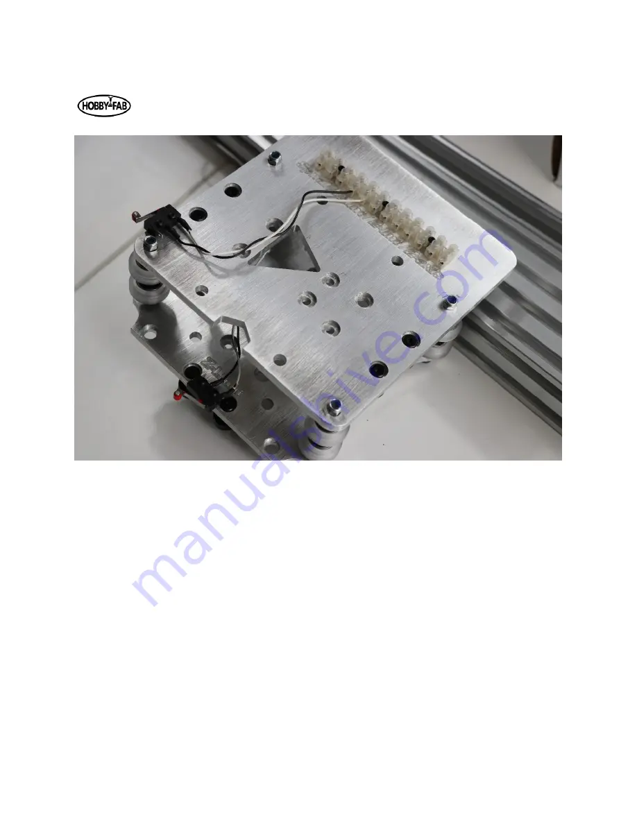
Page 6: ...Last updated 08 13 20108 Rev 9 6 Limit switch and barrier block shown installed ...

Page 7: ...s 12 3mm Spacers 2 M5x20 2 M5x25 16 Note that all wheels are installed with eccentric spacers in this step to allow adequate room for the Z gantry To begin assembly note that one side of the plate has recesses We will be installing bolts from this side and the eccentric and regular spacers on the other side Also you will note one side of the inner gantry wheel holes is smaller in diameter we call ...

Page 8: ...Last updated 08 13 20108 Rev 9 8 Install the outer wheels and turn the eccentrics until the outer wheels touch the C beam The ACME block is installed in the same fashion as the first step ...

Page 9: ...Last updated 08 13 20108 Rev 9 9 Note limit switch on bottom of plate these wires will remain loose till install ...

Page 10: ...ference wheels as a base and adjust the eccentrics to touch the inside of the sample beam 250mm length Z Continue by installing the ACME block with the supplied 3mm spacers and M5 x 20mm bolts Again it is a good idea to adjust the tension on the ACME block at this time Note this plate is completely remodeled but the assembly remains the same ...

Page 11: ...Last updated 08 13 20108 Rev 9 11 Notch in plate faces down Limit switch on the left hand side looking at the plate ...

Page 12: ...pdated 08 13 20108 Rev 9 12 STEP 3 Qty Smw3D Builder Rear XZ Gantry Plate 1 Adjustable Tension Anti Backlash Nut 1 Mini Delrin Wheels 8 3mm spacers 2 m5x20 2 m5x25 8 6mm Spacers 4 6mm mini eccentric spacers 4 ...

Page 13: ...entrics have them spaced out slide your 250mm length C beam in and adjust the tension evenly Turn of a revolution on the two eccentrics on one axle at a time Start with the far left top corner then go to the top right corner then the right bottom then the left bottom If all are touching you re done If not repeat by turning each axle eccentrics of a rev again Once the outside wheels all touch move ...

Page 14: ...Last updated 08 13 20108 Rev 9 14 STEP 4 Qty Smw3d Builder Large Xtreme Wheels 16 9mm Spacers 8 6mm Mini Eccentric Spacers 16 M5x60 8 ...

Page 15: ...e cautious with these Do not try to bend them or force them open with excessive force Simply slide the clamp on the end of the C Beam install with a T nut and M5 x 8 screw on both sides and tighten The clamp will be tight when installing the spindle You can gently spread the clamp by hand and slide in the spindle The clamps should be on the stainless caps of the spindle STEP 5 Qty Smw3d Builder 80...

Page 16: ...8 Rev 9 16 Note you can see both limit switches from the back view The Z limit wires can now be moved directly up in relation to the picture and through the notch in the rear plate and inserted into the Z Axis screw terminals ...

Page 17: ... of the machine at this time and debate if there will be an advantage to the motor being mounted on one side or the other for space reasons The M5x15mm bolts will hold the beams to the Y gantry plates The bearings will fit into the recesses in the outside of the Y gantry plates The ACME will thread through the anti backlash nut on the X gantry we built in a previous step Prior to installation it i...

Page 18: ...ted 08 13 20108 Rev 9 18 STEP 6 Qty Smw3d Builder M5x15 10 M5x55 2 1 5in spacers 2 608ZZ Bearing 2 8mm lock collar 1 6 35x8 Coupler 1 1000mm Acme 1 1000mm 20x20 1 1000mm C Beam 1 NEMA 23 2 8A 1 Shim 12 5x8x1 5 2 ...

Page 19: ...Last updated 08 13 20108 Rev 9 19 ...

Page 20: ...08 Rev 9 20 Above the motor installation is shown Use the two longer bolts and spacers to attach the motor Install the bearing washer and coupler as shown Tighten all set screws on the coupler once the ACME is fully engaged ...

Page 21: ...even bag you will find an ACME nut plate Use this to push the lock collar flush against the bearing and remove any slack from the drive Excessive force is not needed Simply tighten down the nut plate while holding the coupler on the other end then tighten the set screw Remove the nut plate afterward ...

Page 22: ...st but we will be mounting end caps instead of Y gantry plates Step 7 Qty Smw3d Builder NEMA 23 2 8A 2 6 35x8 Coupler 2 Machined end corner caps 4 Lock collar 2 608ZZ 4 C Beam 1000mm 2 1 5 spacers 4 M5x55mm bolts 4 M5x20mm bolts 20 Single corner bracket 4 M5 nuts 4 1000mm ACME 2 ACME flange nut 1 Shim 8mm 4 Each corner bracket holds the ACME in place and retains the build to the board ...

Page 23: ...dated 08 13 20108 Rev 9 23 Front machined end caps shown above The L shape should face the inside of the C of the beam Rear machined plates have been modified installation is the same but now has wiring blocks ...

Page 24: ...ler board near the last step when we can square the build If you choose to install them now thread the ACME in until the Y gantry plates are the same distance from the corner plates Then install the corner plates square with the front edge of the spoiler board Y rear machined end plates ...

Page 25: ...antry with the spindle and prepare to install this with the 250mm ACME This axis is in compression versus the previous tension set ups Step 8 Qty Smw3d Builder C beam end plates 2 M5x55mm 2 1 5 spacers 2 250mm ACME 1 688zz 2 6 35mm x 8mm coupler 1 Nema 23 1 M5x25mm 8 8mm Lock Collar 2 Shim 12 5x8x1 5 2 ...

Page 26: ...m and bearing into the recess on the plate Attach the motor as in the previous step On the lower portion perform the same task Slide a lock collar bearing and shim then the plate over the bottom of the ACME Lock the axis in place by tightening the set screw on the lower lock collar Watch the play in the Z final assembly You should not be able to wiggle the spindle up and down Sometimes it is easie...

Page 27: ...Last updated 08 13 20108 Rev 9 27 ...

Page 28: ...Last updated 08 13 20108 Rev 9 28 ...

Page 29: ...e cable chain down either the left or right side of the build Mount one end to the y gantry plate One plate will have a threaded hole in the middle of the hobby fab logo this is for the Y cable chain Reduce the Y cable chain to half the shipped length You will need to remove one end of the cable chain If you remove the proper end you will be left with a hole in the side of the cable chain where th...

Page 30: ...Last updated 08 13 20108 Rev 9 30 ...

Page 31: ...oute wires and cooling hoses through both Install the water tubing by taking the nuts off the top of the spindle Install a hose and route through both cable chains to exit at the rear of the machine Route a hose to your tank and attach to the top of water pump Route another hose to the tank and allow to flow into the tank The video R7v9 provides a good example of a tank you can use If your tank is...

Page 32: ...Last updated 08 13 20108 Rev 9 32 ...

Page 33: ...ps cnc js org docs desktop app Download the appropriate desktop app for your system OS windows etc Open CNC js Look for a connection window on the top left hand side Power the machine Under port hit the refresh button use the drop down to find the USB port A blue button labeled Open is also in the connection window Click this button You should now be connected You must home the machine prior to jo...

Page 34: ...nfiguring Grbl v0 9 Scroll down a bit and you will see a set of numbers 1 through 132 below this is an explanation of what each does Related to the example above if X moves the opposite direction we tell it we would need to set 3 1 based on this information Setting Value Mask Invert X Invert Y Invert Z 0 00000000 N N N 1 00000001 Y N N 2 00000010 N Y N 3 00000011 Y Y N 4 00000100 N N Y 5 00000101 ...

Page 35: ...f the spindle it should turn to the right The machine is set up and ready to be used Play around with the settings Set travel limits set max velocities and accelerations Have a read on our page about How to CNC here https www smw3d com blog how to cnc Read about feeds and speeds here https www smw3d com blog what is the right feeds and speeds for my cnc router kit Explore the machine explore softw...

Page 36: ... suppression equipment close at hand and prepared for an emergency SMW3D Hobby Fab J Tech and affiliated groups hold no liability to property personal or any other damage created from the use of this product The purchase and use of this laser add on system is strictly the end user s liability and responsibility to ensure safe use Specifications Please see the J tech instruction manual for full det...

Page 37: ...wn above on the 400 watt spindle 600w and 800w are identical These holes should center the laser in the Y plane with the spindle center Open the laser package and look for a small bracket that will fix a fan to the back of the diode laser ...

Page 38: ...aser should face downwards with the fan mounted on the bracket with the Sunon logo facing the diode It is advised to install the laser M3 bolts with blue thread lock The laser diode and fan wire should be routed through both the X and Y cable chain and exit near the control box area ...

Page 39: ...Last updated 08 13 20108 Rev 9 39 The laser diode will connect to the driver board on the H3 header and the fan will connect to the fan header ...

Page 40: ...t updated 08 13 20108 Rev 9 40 1 Shown uninstalled for relation Next connection will be the PWM signal Regardless of the GRBL controller sent we will utilize the PWM and signals to control the laser power ...

Page 41: ...o the laser connector connect the other end to the PWM positive and negative connections on the board Polarity matters On the all in one controller the accessory port yellow is PWM blue is PWM Connect the supplied power supply with the barrel connector to the laser driver board The laser add on is now ready for use ...

Page 42: ... gcode into your communication software such as CNC js or bCNC Locate the serial port box in CNC js this is the black box in the middle of the left hand side of the screen bCNC this is the upper right hand corner of the screen a tab called terminal Type and hit enter Note that 32 0 currently Router control is standard in this mode Type 32 1 and hit enter The machine is now in laser mode Making thi...

Page 43: ...nce away from the work piece Set this as your Z 0 When producing gcode for laser use use a very small Z depth of cut DoC such as 001 units Also clearance height can be reduced to 0 for maximum efficiency The number one mistake we make here is forgetting to turn the machine back to router mode After laser operations recall to set 32 0 Any questions please do not hesitate to contact us we will happy...

Page 44: ... dislodged If the shipping box is severely damaged upon receipt please DO NOT PLUG THE BOX INTO A WALL OUTLET The box is internally grounded and fused for both AC and DC but your safety is top priority a damaged box should not be used SMW3D Hobby Fab and related affiliates hold no responsibility for damage to equipment or persons by using this product Be safe be smart build CARE The control box is...

Page 45: ... Y Axis Black White Y axis limit switch Yellow Blue 1A 1B stepper motor pair Red Green 2A 2B YNL this is only needed on gantry style machines with two Y motors YNL stands for Y axis no limit the black and white wires are not present on this axis Yellow Blue 1A 1B stepper motor pair Red Green 2A 2B Z Axis Black White Z axis limit switch Yellow Blue 1A 1B stepper motor pair Red Green 2A 2B NOTE If y...

Page 46: ...ws power to the control board Step 3 Plug in a USB style Mouse and Keyboard to either USB port on the front Step 4 Plug an HDMI monitor into the port on the face Step 5 Plug the 110VAC cable into the fused connection on the far left Step 6 Turn on the master switch ACC X Y YNL Z ...

Page 47: ...splay a logo while boot up is taking place Once this splash screen is complete the system will open to bCNC and connect automatically THE MACHINE MUST BE HOMED PRIOR TO JOGGING There is a home button on the control tab at the upper left hand corner Click home You should expect the Z axis to go up touch the limit switch go down then come back up After this action X and Y should both start moving to...

Page 48: ...d hit enter and your current 3 1 and your Z was going the wrong direction try 3 6 hit enter Try homing the machine again Continue the above till all 3 axis are homed Post the above exercise and homing you are ready to CNC Play around inside bCNC and read more at the links provided within this document Setting workpiece zero is as simple as jogging to the location and clicking the X 0 y 0 z 0 butto...

Page 49: ...Last updated 08 13 20108 Rev 9 49 Please email or call if there are any issues we are happy to assist contact hobby fab com or 346 333 6500 ...

Reviews: