background image

3

inTRODUcTiOn

Fcc cOMPLiancE STaTEMEnT

This equipment has been tested and found to comply with the limits for a Class B digital device, pursuant to Part 15 of the FCC Rules. 

These limits are designed to provide reasonable protection against harmful interference in a residential installation. This equipment 

generates, uses, and can radiate radio frequency energy and, if not installed and used in accordance with the operating instructions, 

may cause harmful interference to radio communications, however, there is no guarantee that interference will not occur in a particular 

installation. If this equipment does cause harmful interference to radio or television reception, which can be determined by turning the 

equipment off and on, the user is encouraged to try to correct the interference by one or more of the following measures:

l

  Reorient or relocate the receiving antenna.

l

  Increase the separation between the equipment and the receiver.

l

  Connect the equipment into an outlet on a circuit different from that to which the receiver is connected.

l

  Consult the dealer or an experienced technician for help.

This device complies with Part 15 of the FCC Rules and with RSS-210 of Industry Canada. Operation is subject to the following two conditions:

1)  This device may not cause harmful interference, and....
2)  This device must accept any interference received, including interference that may cause undesired operation.

WARNING:

 Changes or modifications made to this equipment not expressly approved by the party responsible for compliance may 

void the FCC authorization to operate this equipment.

RF Exposure Statement
The Aero Sport 5 transmitter has been tested and meets the FCC RF exposure guidelines when used with the accessories supplied or 

designated for this product, and provided at least 20cm separation between the antenna the user's body is maintained. Use of other 

accessories may not ensure compliance with FCC RF exposure guidelines. 

We appreciate your purchase of the Hobby People Aero Sport 5 2.4GHz FHSS-1 radio control system. This Operating Manual is intended 

to acquaint you with the features of your new radio control system and how to use these features to get the most from your experience.

Please read this Operating Manual carefully so that you may obtain maximum success and enjoyment from the operation of your new 

Aero Sport 5 2.4GHz FHSS-1 radio control system. This radio control system has been designed for the utmost in comfort and precise 

control of your aircraft. We wish you the best of success and fun with your new purchase.

Please note that due to differences in the implementation of 2.4GHz technology among different manufacturers, only Airtronics 

brand 2.4GHz FHSS-1 aircraft receivers are compatible with your radio control system.

aDDiTiOnaL REcEivER inFORMaTiOn

Additional  receivers  can  be  purchased  and  paired  with  the Aero  Sport  5  transmitter  through  the  Binding  operation. All Airtronics 

2.4GHz FHSS-1 aircraft receivers are compatible with the Aero Sport 5 transmitter. For more information on the current receivers 

available, please visit your local Hobby People retail store or our website at http://www.hobbypeople.net.

This radio control system operates on the 2.4GHz frequency band. The 2.4GHz connection is determined by the transmitter and 

receiver pair. Unlike ordinary crystal-based systems, your aircraft can be used without frequency control.

This is a high-output full-range radio control system that should well exceed the range needed for any model aircraft. For safety, the 

user should perform a range check at the area of operation to ensure that the radio control system has complete control of the aircraft 

at the farthest reaches of the operational area. A range check can be accomplished using Low-Power Mode. For more information, 

see page 14.

TRanSMiTTER SignaL RangE

Summary of Contents for Aero Sport 5

Page 1: ...1...

Page 2: ...cautions Page 5 AMA Information Page 5 Features and Specifications Page 6 System Features Page 6 System Specifications Page 6 Servo Recommendations Page 6 Features Familiarization Page 7 Transmitter F...

Page 3: ...tween the antenna the user s body is maintained Use of other accessories may not ensure compliance with FCC RF exposure guidelines We appreciate your purchase of the Hobby People Aero Sport 5 2 4GHz F...

Page 4: ...uency control transmitter precautions l Turn the transmitter ON first and then turn the receiver ON After using your model turn the receiver OFF first then turn the transmitter OFF It can be dangerous...

Page 5: ...during use Make sure that the receiver servos battery holder and switch harness connectors are securely fitted l The receiver is susceptible to vibration and moisture Take appropriate measures to prot...

Page 6: ...42oz in 3 0kg cm 4 8v 53oz in 3 8kg cm 6 0v Speed 0 20 sec 60 4 8v 0 16 sec 60 6 0v Dimensions 1 54 x 0 79 x 1 42in 39 1 x 20 0 x 36 0mm Weight 1 59oz 45gr 94102Z Standard Bushing 94162Z High Torque...

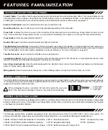
Page 7: ...or Control Stick Throttle Rudder Control Stick Rudder Trim Lever Throttle Trim Lever Aileron Trim Lever Elevator Trim Lever Power LED Red Bind LED Green Neck Strap Anchor The transmitter antenna is ad...

Page 8: ...im Antenna Transmits the signal from the transmitter to the receiver in your aircraft The Antenna should be pivoted into the vertical position during use When not in use the Antenna should be collapse...

Page 9: ...g gear or the flaps on your aircraft Servo Reversing Switches Used to electronically switch the direction of servo travel Servo Reversing is featured on the Elevator Aileron Throttle and Rudder channe...

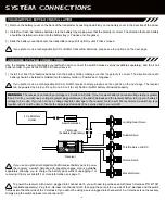
Page 10: ...Harness If you will not be using a servo plugged into channel slot 5 a Y Harness is not necessary Simply plug the switch harness into channel slot 5 If you prefer to use a rechargeable Ni Cd or Ni MH...

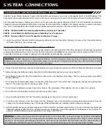
Page 11: ...transmitter could be damaged WARNING An after market peak detection charger and or cycler should NOT be used to charge the optional rechargeable batteries through the transmitter The circuitry within...

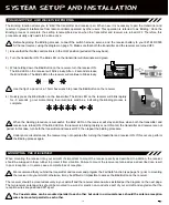
Page 12: ...illuminate solid green 4 Quickly press the Bind Button on the transmitter The Bind LED on the receiver will blink rapidly for 3 seconds go out momentarily then illuminate solid blue indicating the Bi...

Page 13: ...rcraft keep the receiver antenna wires as far away from the motor battery and electronic speed control ESC as possible l When installing the receiver the antenna reception wires the thin tip at the en...

Page 14: ...attery connections are correct and secure Check to ensure that the receiver antenna wires are correctly mounted as described previously 3 When satisfied that the system is operating correctly turn the...

Page 15: ...d Fail Safe settings re bind the transmitter and receiver pair For more information see page 12 The length of the control sticks can be adjusted to best suit the way you hold them In general pilots wh...

Page 16: ...annel mixing The Channel Mixing function allows you to quickly set up the transmitter s low level mixing based on the type of aircraft you re flying Options include Normal Delta Elevon and V Tail For...

Page 17: ...sticks are moved to their stops that the servos do not buzz and that the control surfaces do not move any more than the maximum control throw necessary If the servos are buzzing this means that they...

Page 18: ...ttery voltage Receiver antennas not mounted correctly in your model Transmitter antenna not angled to optimum position Transmitter in Low Power Range Check mode Incorrect Servo Reversing switch positi...

Page 19: ...dulation type which transmits data across the entire frequency spectrum by transmitting data on different channels at an extremely fast interval Landing Gear Switch Used to control the operation of th...

Page 20: ...duct For More Information or Product Service Contact Global Services 18480 Bandilier Circle Fountain Valley CA 92708 Telephone 714 963 0329 Fax 714 964 6236 Email service globalhobby net http globalse...

Reviews: