background image

Page 7

BECOmING FAmILIAR WITh YOUR OUTLAW RTR BUGGY

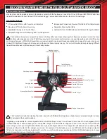
Antenna:

 Transmits the signal from the transmitter to the receiver in the model. The antenna should be fully extended during use. When 

collapsing the antenna after use, be careful not to bend it.

Battery Compartment:

 Houses the 8 'AA' Alkaline batteries that power the transmitter.

Charging Jack:

 Used for onboard charging of optional Ni-Cd or Ni-MH batteries.

Do not attempt to charge Alkaline batteries. Only Ni-Cd or Ni-MH batteries (available separately) should be charged through the 
Charging Jack, using only the recommended type of charger. For more information, see the bottom of the previous page.

Crystal:

 Controls the frequency (channel number) of the transmitter. You can change crystals in both the transmitter and the receiver 

so that you and your friends can drive at the same time. No two radio control systems nearby can be operated on the same channel 
number at the same time without interference. The transmitter and receiver use 27MHz crystal sets.

Grip:

 The Grip is molded in an ergonomic shape for increased comfort, control and feel.

Power Indicator Lights:

 Indicate the current status of the transmitter batteries. When the all three Power Indicator Lights are illuminated 

the batteries have sufficient capacity to power the transmitter safely. If only the red and yellow Power Indicator Lights are illuminated the 
batteries have only limited capacity to power the transmitter. In this case, the batteries should be replaced as soon as possible. If only 
the red Power Indicator Light is illuminated, the batteries are depleted and should be replaced (or recharged, if using optional rechargeable 
Ni-Cd or Ni-MH batteries). Do NOT attempt to use the transmitter if only the red Power Indicator Light is illuminated.

Power Switch:

 Turns the transmitter 'ON' and 'OFF'.

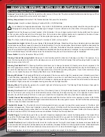
Steering Channel Reversing Switch:

 Allows you to electronically switch the direction of steering servo travel. For example, if you 

move the steering wheel to the right and the steering servo moves to the left, flip the Steering Channel Reversing Switch to make the 
steering servo move to the left.

Steering Dual Rate Dial:

 The Steering Dual Rate dial allows you to change the amount of steering servo travel compared to the 

amount of physical movement of the steering wheel. For example, by increasing the Steering Dual Rate (moving the dial forward), you 
can make the steering servo travel more which might prevent your model from pushing during turns. If your model oversteers during 
turns, you can reduce the amount of Steering Dual Rate (move the dial backward).

Steering EPA Knobs: 

The Steering EPA (End Point Adjustment) Knobs are used to adjust the desired amount of steering servo travel 

in both directions independently. This makes it possible to balance servo travel in both directions by either increasing or decreasing 
servo travel in either direction. One knob (EPA-ST Left) increases or decreases steering servo travel in the Left direction and the second 
knob (EPA-ST Right) increases or decreases steering servo travel in the Right direction.

Steering Wheel:

 Proportionally operates the model's right and left steering control. The Steering Wheel features a foam grip for 

increased comfort, control and feel.

Steering Trim Knob:

 Used to adjust the center trim of the steering channel. Turning the knob forward (clockwise) increases steering 

trim in one direction and turning the knob backward (counter-clockwise) increases steering trim in the opposite direction. Make 
adjustments with the Steering Trim Knob to make your model drive in straight line without any input from the steering wheel.

Throttle Channel Reversing Switch:

 Allows you to electronically switch the direction that the motor operates in relation to the throttle 

trigger. For example, if you pull the throttle trigger to accelerate forward, but the model goes in reverse, flip the Throttle Channel Reversing 
Switch to make the model accelerate forward.

Throttle EPA Knobs: 

The Throttle EPA (End Point Adjustment) Knobs are used to adjust the desired amount of throttle in both 

directions independently. This makes it possible to adjust the amount of throttle in both the Forward and Reverse directions by either 
increasing or decreasing throttle in either direction. One knob (EPA-TH Backward) increases or decreases throttle in the Reverse direction 
and the second knob (EPA-TH Forward) increases or decreases throttle in the Forward direction.

Throttle Trigger:

 Controls the speed of the model, both forward and backward. Also controls the braking ability of the model. When 

you pull the throttle trigger back toward you, the model accelerates forward. When you push the throttle trigger away from the you, the 
model brakes. When you release the throttle trigger momentarily, then push it away from you again, the model goes in reverse.

Throttle Trim Knob:

 Used to adjust the center trim of the throttle channel. Turning the knob forward (clockwise) increases throttle trim 

in one direction and turning the knob backward (counter-clockwise) increases throttle trim in the opposite direction. Make adjustments 
to the Throttle Trim Knob so that the model doesn't move (the motor is 'OFF') when the throttle trigger is in the neutral position.

Wrist Strap Anchor:

 Used to connect an optional wrist strap (available separately) to the transmitter.

n  

Transmitter Overview, Continued....

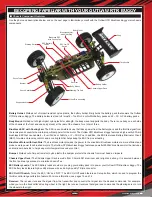
Summary of Contents for Outlaw 4WD

Page 1: ...Page 1 Kit Product 143400...

Page 2: ...ion with this lightweight simple 4WD design Inspired by 1 10th scale 4WD buggies the Outlaw RTR Brushless Buggy makes 1 8th scale truly compatible with the indoor track And it s fun too A powerful bru...

Page 3: ...nectors that you use While the power system will provide good power using a lower quality battery to take full advantage of the power available we recommend the use of a high quality battery and conne...

Page 4: ...charge Li Po batteries near any flammable material l DO NOT use or charge Li Po batteries if they are hot to the touch l DO NOT leave Li Po batteries in direct sunlight or in a hot car or storage are...

Page 5: ...ery Requirements The Outlaw RTR Brushless Buggy can be powered using either one 6 7 cell Ni Cd or Ni MH battery pack or it can be powered using one 2 3 cell Li Po battery pack Recommended Battery Pack...

Page 6: ...ng Trim Knob and all four EPA End Point Adjustment Knobs feature a molded indicator on them to help identify their center positions Continued On Next Page Upgrading your transmitter to use rechargeabl...

Page 7: ...backward Steering EPA Knobs The Steering EPA End Point Adjustment Knobs are used to adjust the desired amount of steering servo travel in both directions independently This makes it possible to balanc...

Page 8: ...efficient and produce more power than brushed motors The Outlaw RTR Brushless Buggy features a powerful 2950kV brushless motor that includes an aluminum heat sink to help keep motor temperatures unde...

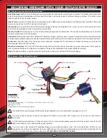
Page 9: ...inner and upper outer suspension components The turnbuckle is threaded allowing you to adjust the camber angle of the front and rear tires Wheel Tire Assembly The Outlaw RTR Brushless Buggy features m...

Page 10: ...eat shrink tubing to insulate the solder joints l Always make sure that you install the body when driving your Outlaw RTR Brushless Buggy If your Outlaw RTR Brushless Buggy flips over the body will he...

Page 11: ...support tube If you re using a hard case Li Po car battery pack with preinstalled 4mm female Bullet connectors an adapter may be included with your battery pack or available separately to plug into th...

Page 12: ...ry pack leave the foam block in place to hold the battery pack securely in position If necessary the foam block can be cut down to fit your particular application using either a pair of scissors or a...

Page 13: ...throttle trigger and the wheels should stop spinning q Push the throttle trigger forward Both the front and rear wheels should spin backward q Release the throttle trigger and the wheels should stop s...

Page 14: ...Buggy flips over the body will help protect the chassis and its components DRIvING YOUR OUTLAW RTR BUGGY The Outlaw RTR Brushless Buggy is simple to drive yet will provide a high level performance and...

Page 15: ...u can make the steering servo travel more which might prevent your model from pushing during turns By reducing the steering dual rate move the dial backward with your thumb you can make the steering s...

Page 16: ...in on the rear tires is fixed at approximately 2 degrees and is not adjustable Straight No Toe Toe In Toe Out By adjusting the spring tension of the shocks you can increase steering sensitivity adjus...

Page 17: ...o push the top of the tires out Camber settings should be measured with the Outlaw RTR Brushless Buggy at its normal ride height PRO TIP For more precise camber adjustments use a dedicated camber gaug...

Page 18: ...rmly q Reinstall the shock spring and spring holders then reinstall the shock onto the lower suspension arm and the shock tower Installation is the reverse of removal Continued On Next Page The slippe...

Page 19: ...from turning use a 7mm open end wrench and tighten the flanged lock nut turn clockwise to tighten the slipper clutch less slip or loosen the flanged lock nut turn counter clockwise to loosen the slipp...

Page 20: ...nion gear 19T will result in quicker acceleration but slower top speed and using a larger pinion gear 23T will result in faster top speed but slower acceleration It s all a matter of experimenting wit...

Page 21: ...rod ends from the steering knuckles q Remove the four 3 x 12mm Countersunk Self Tapping screws from the bottom of the chassis that hold the gearbox in place then remove the two 3 x 8mm Round Head Self...

Page 22: ...inding l Check the electronics for any signs of damage This includes the steering servo receiver motor wiring and electronic speed control l Periodically disassemble the slipper clutch and clean any d...

Page 23: ...ace spur gear B Replace pinion gear C Tighten pinion gear grub screw D Tighten slipper clutch Page 19 E Tighten differential output pinion joint screw s F Replace damaged dogbone s and or drive shaft...

Page 24: ...er crystal F Receiver damaged A Steering channel EPA out of adjustment B Steering Dual Rate out of adjustment A Reinstall batteries Observe correct polarity B Replace or recharge transmitter batteries...

Page 25: ...143630 143634 143634 143662 143689 143662 143634 143634 143662 143689 143632 143634 143663 143644 143663 143644 143644 143644 143668 finished for left side for right side 143632 143630 for front and...

Page 26: ...ront and rear x2 143622 143661 143688 143621 143636 143636 143635 143635 143636 143635 143635 143635 143635 143636 143636 143661 143622 143636 143636 143635 143635 143636 143635 143635 143636 143669 1...

Page 27: ...EMBLy FOUR FRONT GEARBOX AND SHOCK TOWER 143676 143660 143644 143652 143687 143687 143603 143633 143652 143696 143696 143606 143626 SUB ASSEMBLy FIVE REAR GEARBOX AND SHOCK TOWER 143676 143660 143606...

Page 28: ...X FRONT SUSPENSION 143657 143658 143631 143662 143616 143660 143660 143649 143631 143658 143669 143628 143647 143695 143624 143650 143612 143612 143657 143612 143657 143612 143612 143617 143660 143657...

Page 29: ...ASSEMBLy NINE SLIPPER CLUTCH SUB ASSEMBLy EIGHT STEERING SERVO MOUNTING finished finished 143687 143687 Steering Servo CH1 143645 Included with Servo 143662 143645 143611 143678 143608 143608 143608...

Page 30: ...678 143717 143690 143638 143604 SUB 8 145657 143638 143643 143679 143690 143675 143602 143643 SUB 1 143663 143613 143614 143691 143677 143691 143658 SUB 4 143663 143627 143664 143698 143664 143655 143...

Page 31: ...43663 143620 143618 143640 143641 143619 143694 SUB 7 143698 143656 143664 143705 143658 143627 143657 143685 143664 143663 143705 143656 143627 143698 143685 143657 SUB 7 143687 143653 143696 143653...

Page 32: ...bly Complete 143616 Wheel Shafts Front 143618 Wheel Hex Nuts 17mm 143619 Pins for Wheel Hex Adapters 143620 Wheel Hex Hubs 17mm 143613 Steering Tie Rods 143617 Wheel Shafts Rear 143605 Shock Tower Rea...

Page 33: ...8 Motor Mount Set Spur Gear 143639 Spur Gear Metric 48P 66T 143640 Tires Pin Type w Inserts 143633 Differential Assembly Complete 143637 Body Posts Bumper Set 143642 Tires Wheels Mounted 143643 Upper...

Page 34: ...m 143660 Ball Bearings 5x11x4mm 143662 Ball Studs for Steering 143663 Lock Nuts 2 5mm 143664 Ball Studs for Upper Shock Mounts 143657 Balls 4 8mm for Lower Shock Ends 143661 Ball Bearings 10x15x4mm 14...

Page 35: ...ws 3x10mm 143688 Self Tapping Screws 2x9mm 143681 Self Tapping Screws 2 6x8mm 143685 Machine Screws 2 5x14mm 143690 Machine Screws 3x8mm 143691 Machine Screws 2 5x12mm 143692 Self Tapping Screws 2 6x6...

Page 36: ...n parts that are available along with their respective part numbers for easy ordering convenience are described in this section OpTION pARTS LIST Part number descriPtion 143703 Body Clear w Decals 143...

Page 37: ...Page 37 NOTES Continued On Next Page...

Page 38: ...Page 38 NOTES...

Page 39: ...t we need more details pertaining to the service requested l If your Outlaw RTR Brushless Buggy is out of the warranty period you may request an estimate of services at the time you return it for serv...

Page 40: ...Page 40 Features and Specifications are Subject to Change Without Notice All contents 2010 Hobby People All Rights Reserved Revision 1 09 30 2010 Made in China...

Reviews: