WWW.HOBBYEAGLE.COM 8 / 16
Table 2: Output Functions
Function
OUT1
OUT2
OUT3
OUT4
OUT5
Description
INH
Output Disabled
AIL
●
Output for Aileron Servo
ELE
●
Output for Elevator Servo
RUD
●
Output for Rudder Servo
AIL2
●
Output for Aileron 2 Servo
ELE2
●
Output for Elevator 2 Servo
AUX1
Output for AUX1 Channel
AUX2
Output for AUX2 Channel
Notes:
● are the default settings of standard PWM receiver mode.
AUX1
and
AUX2
are both invalid in standard PWM
receiver mode.
OUT5
is always preset to output the
AUX1
channel in PPM or serial receiver mode by default.
Servo Reverse
The
Servo Reverse
function is designed to use for reverse servos, for example, when operating the gyro
in single aileron control mode with two aileron servos connected, it will be impossible to reverse the
servos separately if a reverse servo is being used on one side of the wing. In this case, the
Servo Reverse
function provided by the gyro makes it easy to change the direction of one of the servos. The same also
applies to such applications as two elevator servos, two wing servos of a delta wing or two tail servos of
a v-tail airplane.
Wing Type and Servo Connection
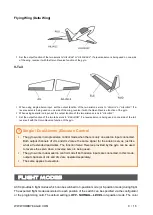
A3S4 supports Standard Fixed-wing, Flying-wing (Delta-wing) and V-Tail.
Always turn off the mixing
function of delta-wing or v-tail in the transmitter because the gyro will provide such mixing
features by itself
. Check the
Servo Monitor
of the transmitter and verify that each stick controls only one
channel.
Standard Fixed Wing
When using single aileron input, set the output function of the two aileron servos to “
AIL
+
AIL
” or “
AIL
+
AIL2
”. If a
reverse servo is being used on one side of the wing, reverse it with the
Servo Reverse
function of the gyro.
When using dual aileron input, set the output function of the two aileron servos to “
AIL
+
AIL2
”.
The same applies to the elevator servos connection.


