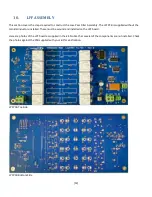
[15]
Build Options
T303 and T304 form a directional coupler used to determine the Hardrock-500’s forward and reflected power. The
coupler can also be used to provide an RF tap or sample of the RF power used by some SDR transmitters to further
linearize the amplifier. If you want to use this option you will need to install a SMA connector in the ‘RF-TAP’ location.
This tap is 30 dB below the RF output and MUST be terminated in 50 ohms for the amp to work correctly.
A negative ALC voltage is available at the ALC location on the PCB. Some transmitters can use an ALC voltage to limit
their output to protect the amplifier. If you want to use this option populate VR301 with a 10K ohm potentiometer and
connect the ALC voltage to the ALC pins.
Assembly Instructions
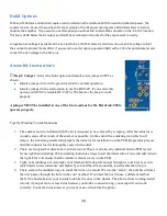
□
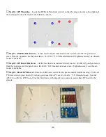
Step 1: Jumper
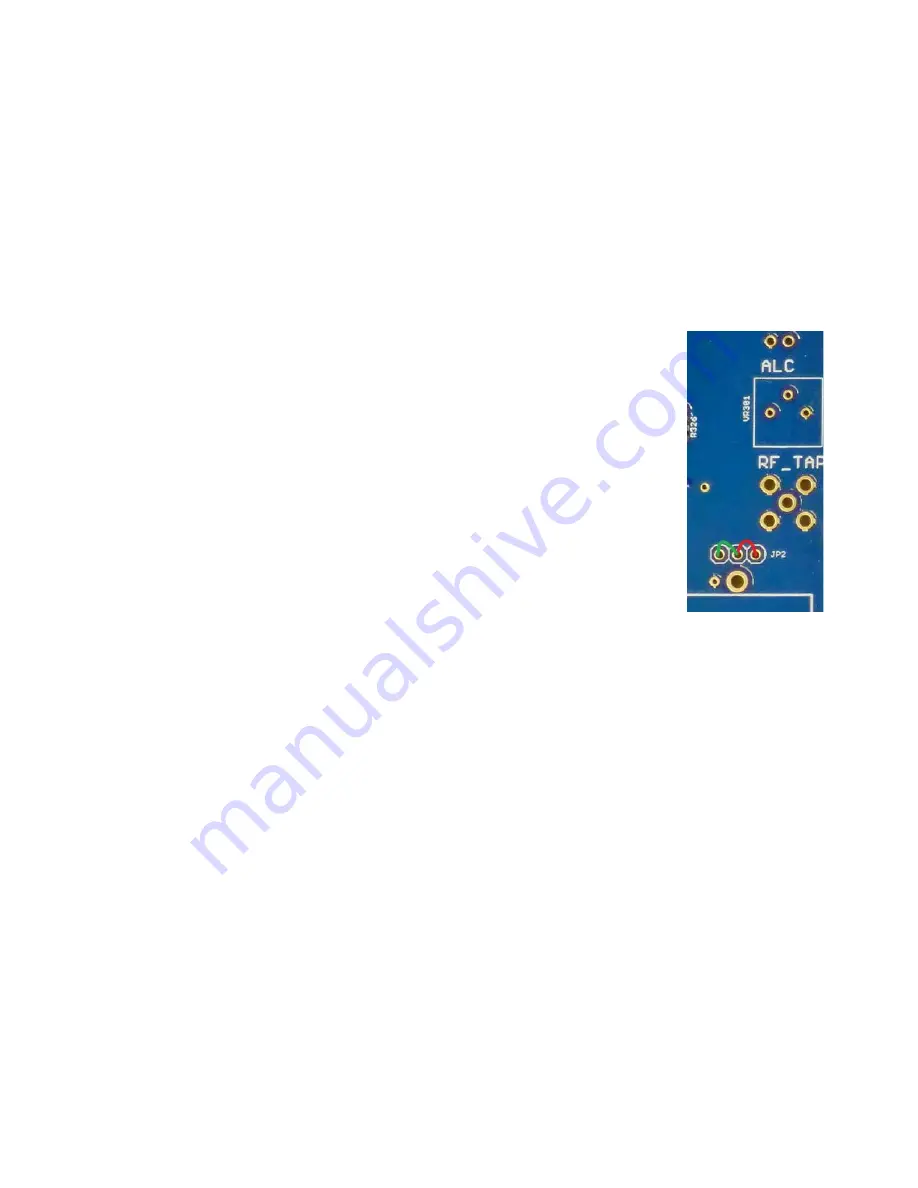
–Select the build option and install a wire jumper in JP2 as
shown.
Install a jumper wire in the green location for normal operation
Install a jumper in the red location to use the RF-TAP. If you select this
option you MUST terminate RF-TAP in 50 ohms for the amp to work
properly
A jumper MUST be installed in one of the two locations for the Hardrock-500 to
operate properly.
Tips for Winding Toroidal Inductors:
1.
The enamel on wire included with the kit is designed to be removed by scraping. After the inductor is
wound, scrape off as much of the enamel as possible, tin the end with a soldering iron which will
remove the remaining enamel and prepare the inductor for installation on the PCB. Repeat this process
until the inductor lead is thoroughly coated with solder.
2.
There are two possible directions to wind a toroid. They are electrically identical but the PCB layout
favors right hand winding. When winding inductors always insert the initial turn of wire and add turns to
the right. This will ensure that the inductors mount nicely on the PCB.
3.
Tight, neat windings not only make your finished kit look professional but tighter coils have less wire
which leads to less resistance and higher Q so bend the wire around the toroid rather than loop it.
4.
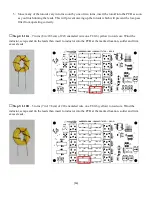
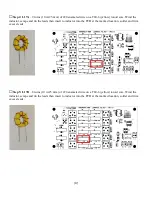
There seem to be multiple ways to count the turns on a toroid. We use the “turns = the number of times
the wire passes through the hole in the core” method. If you feel the need to use a different method
that’s fine but make sure your toroids look like the ones in the photos. The photos show working/tested
toroids; if you put more or less turns because you think I counted wrong, your amp will not work
correctly. Count the turns however you want, make it look like the photo.

