□
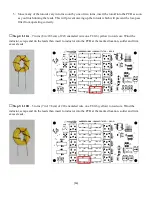
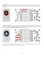
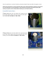
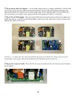
Step 3: Check Capacitor Polarity
–
certain that C201 and C206 are oriented correctly. Solder them to the PCB and
□
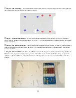
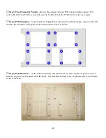
Step 4: PCB Mounting
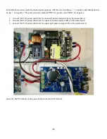
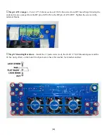
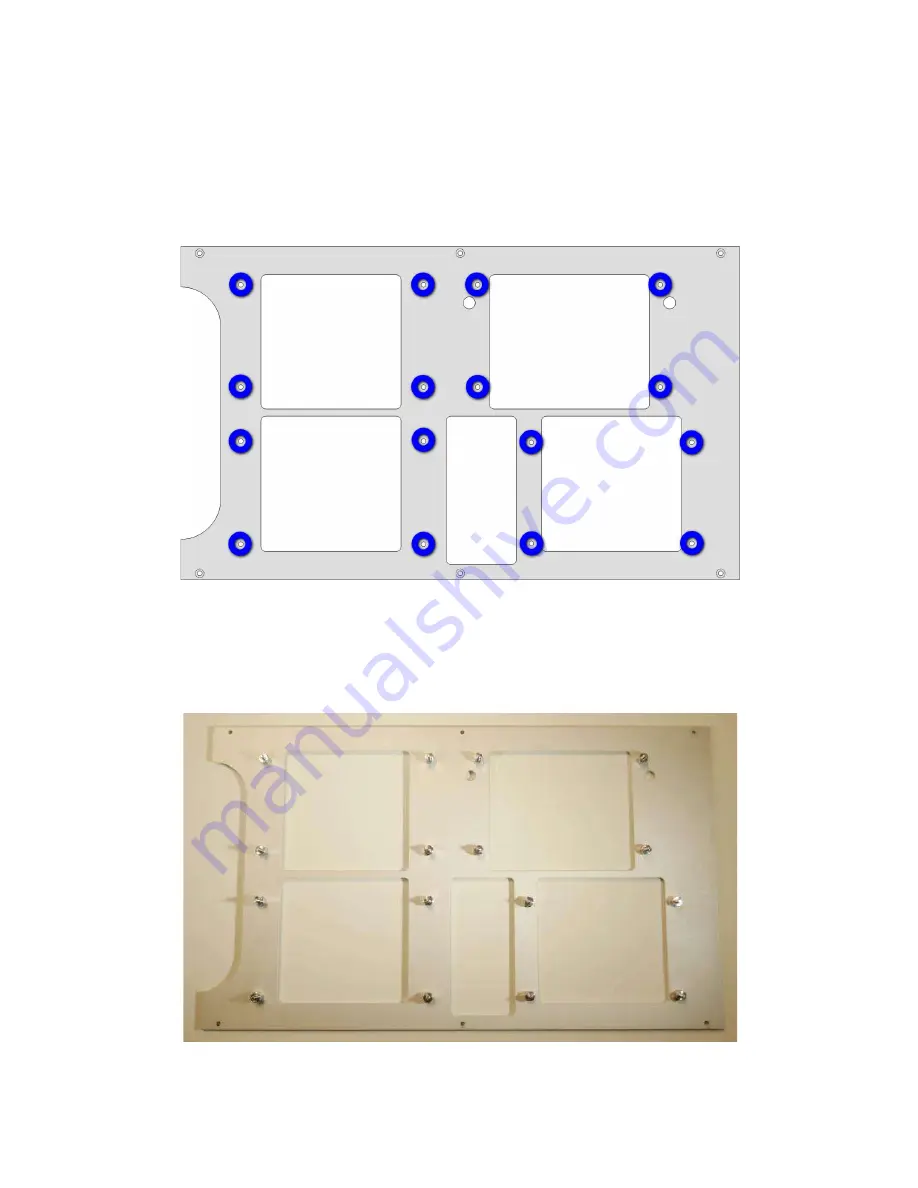
– Locate the Power Supply Panel and orient it so that the large cutout is to the left
and the side with three rectangular cutout in towards the bottom as shown.
□
Step 5: PCB Hardware
– At the sixteen locat
from the opposite side the panel into a
#4
locker if available.
[27]
–Review the pictures and your PCB one more time to make 100%
certain that C201 and C206 are oriented correctly. Solder them to the PCB and trim any excess leads.
Locate the Power Supply Panel and orient it so that the large cutout is to the left
and the side with three rectangular cutout in towards the bottom as shown.
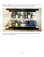
At the sixteen locations indicated in blue, insert a #4-40X1/4"
#4-40 1/4" M-F threaded aluminum spacer
. Tighten securely; use thread
Review the pictures and your PCB one more time to make 100%
trim any excess leads.
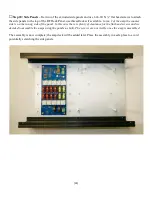
Locate the Power Supply Panel and orient it so that the large cutout is to the left
40X1/4" pan head screw
. Tighten securely; use thread-

