[41]
□
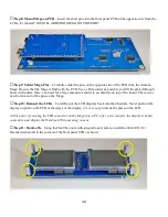
Step 5: Solder the remaining LCD pins
– When you are absolutely certain that the alignment is correct,
solder the remaining pins using as little solder as possible, just fill the plated through holes with solder, there’s
no need for a large amount of solder to accumulate on top of the board. When you are finished soldering, trim
the header leads close to the PCB.
Wear eye protection while cutting the pins as they can become projectiles
when you cut them.
□
Step 6: Remove the LCDs
– Gently remove the LCDs from the header sockets by gently rocking them side-
to side until they come out. Set them in a safe place for reinstallation later.
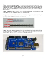
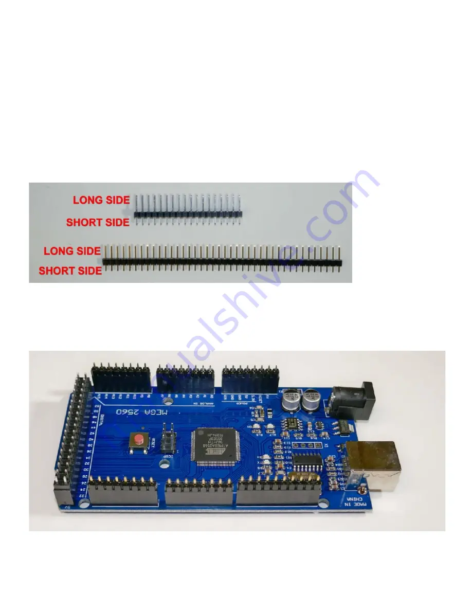
The 40 pin single row headers and the 35 pin dual row headers have a long side and a short side. The long side
goes into the Arduino Mega and the short side goes into the PCB.
□
Step 7: Insert Pins
– Insert the dual header into the dual row receptacle on the Arduino Mega. Use the 40
pin single row headers and break off the appropriate number of pins for each of the single row receptacles on
the Arduino Mega. Make sure that every connection on the Mega has a header pin.

