[42]
□
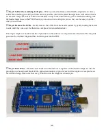
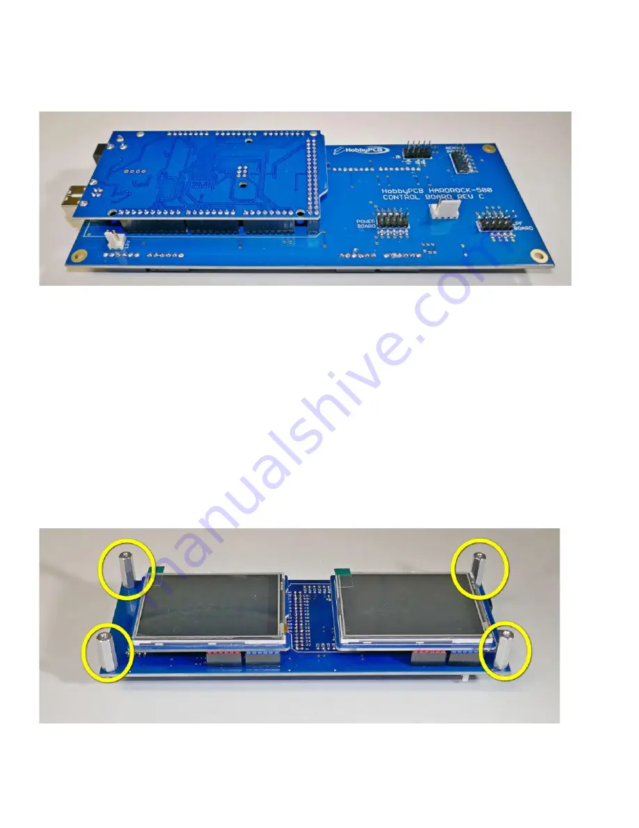
Step 8: Mount Mega on PCB
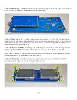
– Insert the short pins into the front panel PCB on the opposite side from the
LCDs, it’s labeled “INSTALL ARDUINO MEGA ON THIS SIDE”.
□
Step 9: Solder Mega Pins
– Carefully solder the pins on the opposite side of the PCB from the Arduino
Mega. Be sure that the Mega is flush with the PCB. Use as little solder as possible, just fill the plated through
holes with solder, there’s no need for a large amount of solder to accumulate on top of the board. There is no
need to trim and of the pins on the Mega.
□
Step 10: Reinsert the LCDs
– Carefully put the LCD displays back into their headers. Never push on the
display on push on the PCB at the edges of the display, it’s very easy to break the glass on the LCD.
At this point, if you plug the USB connector on the Mega into a PC, after a few seconds, the displays should
come alive and display the Hardrock-500 operating screens.
□
Step 11: Stand-offs
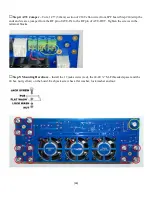
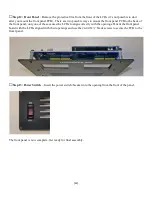
– Using the#4-40 hex nuts with integral lock washers, install the 4#4-40 X 3/4”
threaded stand-offs in the corners of the front panel PCB as shown:

