[53]
□
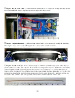
Step 18: Amp In RF Jumper
– Cut a 5” (13cm) piece of RG-316 coax and prepare the ends in the same
manner.
□
Step 19: Input RF Jumper
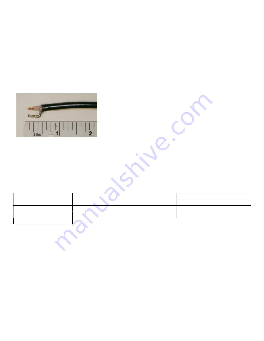
– Cut a 11” (28cm) piece of RG-58 (large, black) coaxial cable. Strip ¾”
(18mm) of the outer jacket from both ends. Be careful not to damage the shield wires. Unbraid the outer shield
with a toothpick or similar item and gather the shield wires to one side. Remove 3/8” (11mm) of the dielectric
from the center conductor. Use pliers for form the center conductor into a tight “u” shape. Tin the shield with
solder.
Be careful because the RG-58 dielectric will melt and deform when it gets hot so keep the solder at least
1/8” (4mm) away from the dielectric and outer jacket.
Form the shield so it will fit in the terminal blocks and
trim the end.
□
Step 20: Amp In RF Jumper
– Cut a 9” (23cm) piece of RG-58 coax and prepare the ends in the same
manner.
□
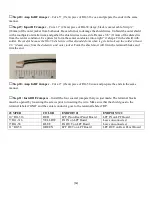
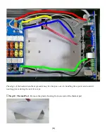
Step 21: Install RF Jumpers
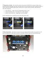
– Install the four coaxial jumpers that you just made. The terminal blocks
must be opened by loosening the screws prior to inserting the wire. Make sure that the shield goes to the
terminal labeled ‘GND’ and the center conductor goes to the terminal labeled ‘RF’.
JUMPER
COLOR
ENDPOIT #1
ENDPOINT #2
10” RG-316
RED
LPF IN on Rear Panel Board
LPF IN on LPF Board
5” RG-316
YELLOW
PA IN on LPF Board
Leave unconnected
9” RG-58
BLUE
PA OUT on LPF Board
Leave unconnected
11” RG58
GREEN
LPF OUT on LPF Board
LPF OUT on Rear Panel Board

