[58]
□
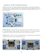
Step 26: VRF2933
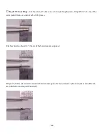
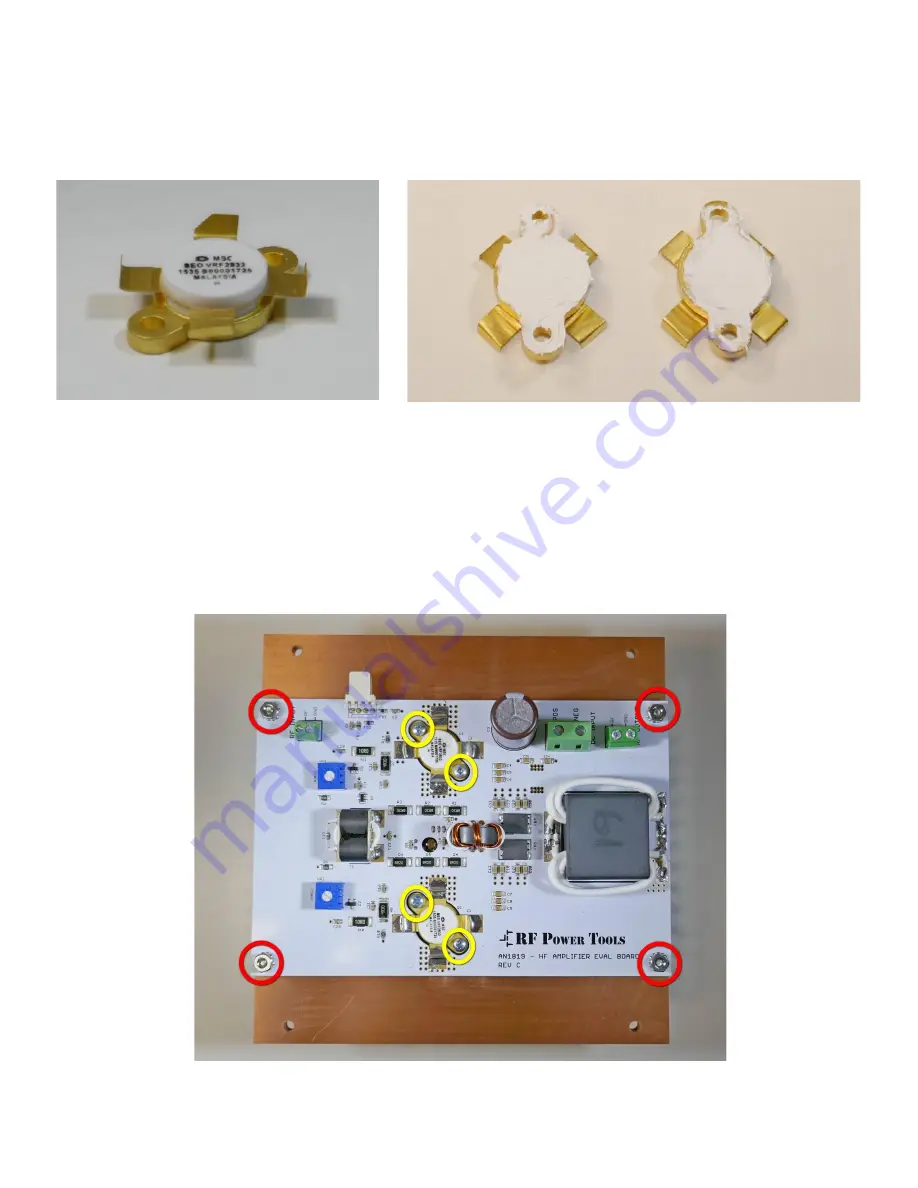
– Bend the ends of the tabs of the VRF2933 MOSFETs upwards at a 90 degree angle.
This makes replacing the VRF2933’s much easier. Put a thin coat of heatsink compound on the back of each
VRF2933.
□
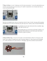
Step 27: AN1819 Board
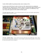
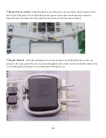
– Place the AN1819 board on the heat spreader, make sure that the temperature
sensor (U1) goes into the large hole in the heat spreader. Secure the AN1819 board to the heat spreader using
four #4-40 hex nuts with integral lock washers (red circles). Place the VRF2933 MOSFETs in their proper
locations aligning the drain tabs (the tabs with the cut-off corner) with the ‘D’ on the circuit board. Secure the
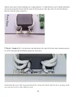
MOSFETs using four #4-40 X ½” screws (yellow circles). Solder the tabs on the MOSFETs by patiently
applying the soldering iron to the PCB next to the tab and applying a SMALL amount of solder to the PCB pad
and waiting for the solder to flow between the PCB and the MOSFET tab. Do not worry about applying too
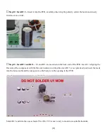
much heat to the MOSFET, it is attached to a massive heatsink. Solder the leads of U1 and trim off any excess.

