[59]
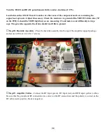
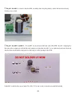
Turn the BIAS1 and BIAS2 potentiometers fully counter-clockwise (CCW).
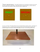
Look between the AN1819 board to make sure that none of the component leads are contacting the
copper heat spreader. Adjust if necessary. Check the resistance to ground of the VRF2933 drain tabs (‘D’
on the PCB) it should be VERY high but you are measuring C3 and meters react differently to large
caps. The gate tabs (opposite the drain) should read 10K to ground.
□
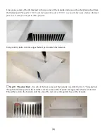
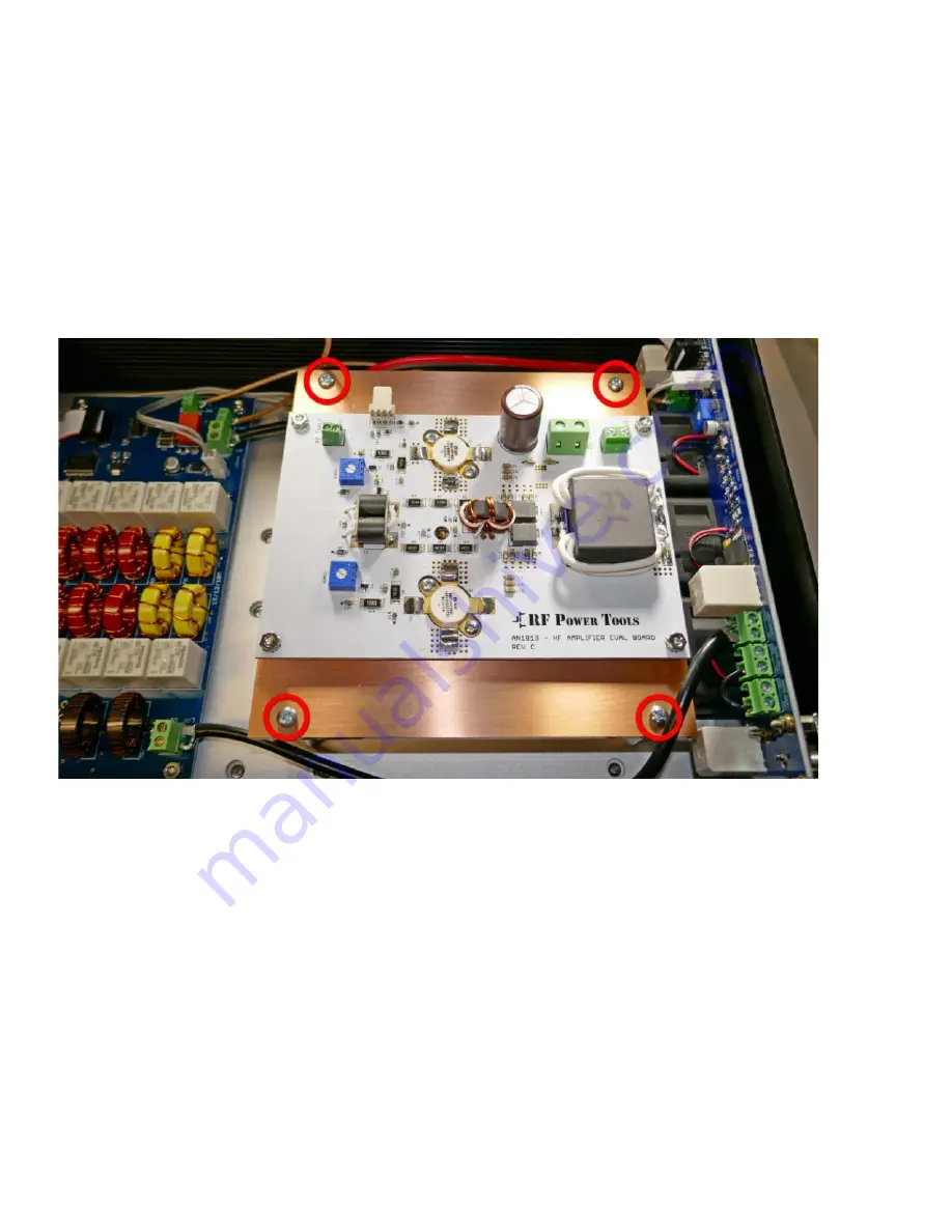
Step 28: Heatsink Assembly
– Place the heatsink assembly into the top of the amplifier support package
and secure with four #6-32 X ½” screws.
□
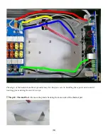
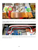
Step 29: Amplifier Cables
– Connect the RF Input (green), DC Input (red), and RF Output (yellow) cables.
Be sure that the ground and RF connections are correct on the RF connections and the polarity is correct on the
DC cable (red is positive, black is negative).

