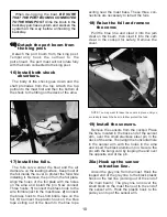
ASSEMBLY INSTRUCTIONS
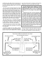
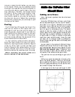
KNOTS TO USE
FIGURE 8 KNOT
BOWLINE KNOT
HALYARD KNOT
CLEATING OFF A LINE
1.
2.
FIGURE 8 KNOT
AT END OF LINE
4
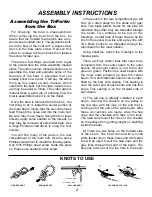
Assembling the TriFoiler
from the Box
For shipping, the boat is disassembled.
When removing the boat from the box, be
aware that the forward foam block has a ply-
wood sheet molded into it. The plywood is bolt-
ed to the bow of the boat with a single screw
which is the bow plate screw. Remove this
screw to remove the foam block then replace
the screw for later use.
There are a few things you need to do to get
to the point where the video assembly manual
starts. The video owners manual shows how to
assemble the boat and explains some of the
features of the boat. It assumes that you
already know how to sail. It will say the same
thing as this paper owners manual, which
came with the boat, but the video owners man-
ual may be easier to follow. The video owners
manual does a good job of showing how the
boat is assembled once it is on the trailer.
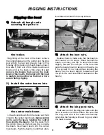
Once the boat is removed from the box, the
first thing to do is install the center portion of
the main beam. Insure that the six control lines
feed through the holes and into the main hull.
Be sure they move freely. Using the four large
screws, apply some sealant to the threads so
they may be removed at some later date. Use
a large Phillips screwdriver to snug the four
screws.
You will find many of the parts in the rear
compartment of the main hull. Use the same
Phillips screwdriver to install the forestay plate.
One 5/16 Phillips head screw holds this plate
on. Please use sealant on this screw.
In the pouch in the rear compartment you will
find: Two drain plugs for the amas with gas-
kets, Two black plastic hooks for the blue foil
retraction lines after they are threaded through
the beam, Two telltales to be put on the
forestays, a small tube of Super Glue to fix the
knot in the sensor bow line and a grey line with
Two brass hooks to be threaded through the
main beam for the mast rotation.
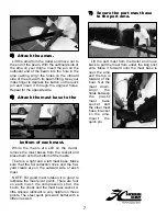
Using shackles, attach the forestays to the
forestay plate.
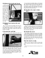
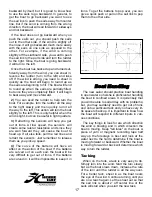
There are Four control lines that need to be
connected from the center beam to the outer
beams. All are color coded, ie, red to red and
green to green. Position the outer beams with
the inner ends propped up near the center
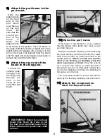
beam. Port and starboard beams can be iden-
tified by the bow wire casting. This casting is
near the outer end of each beam and has four
holes. This casting is on the forward side of
each beam.
1)
The red line is already installed in each
beam. Connect the shackle on the pulley to
the red rope with the loop on the end that is
coming out of the end of the outer beam. After
these connections are made, wrap the hog
rings and the shackles with tape on all lines.
The tape will prevent the lines or the shackle
on the pulleys from getting caught on anything
inside the beam.
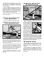
2)
There are two holes on the forward side
of the beam. The boat comes with a small
white feeder line in these holes and this feeder
line will be used to pull the blue lines and the
grey lines through that part of the beam. The
blue line exits out of the top hole in the beam
Summary of Contents for TriFoiler
Page 1: ...ASSEMBLY MANUAL...


