background image

HOBO MX Water Level Logger (MX2001-0x) Manual


U.S. and International Sales: 1-508-759-9500 4 

www.onsetcomp.com 


LED.

 Remove the end cap from the top end to view the 

red LED below the top edge of the circuit board. This LED 
blinks every second while logging and every 8 seconds 
when the logger is configured to start on a specific 
date/time or on the next logging interval. The LED also 
blinks once when you press the password reset button and 
blinks quickly multiple times when the batteries are 
installed. 

When you finish connecting the three components and deploy 
them together, you can configure the logger or download data 
to your mobile device without having to pull the logger up to 
the surface. 

Factory Calibration 

The pressure sensors in the sensor end are individually 
calibrated. During calibration, raw pressure sensor data is 
collected at multiple pressures and temperatures over the 
calibrated range of the logger (see 

Specifications

). This data is 

used to generate calibration coefficients stored in the sensor 
end’s non-volatile memory. The calibration coefficients are 
checked to be sure the logger meets its stated accuracy over 
the calibrated range. The pressure sensor can be used at 
pressures and temperatures that are outside of the calibrated 
range, but its accuracy cannot be guaranteed. 

Important:


Never exceed the burst pressure of the sensor!


Setting up the Logger 

Follow these steps to begin using the logger. After completing 
steps 1–4, we recommend you perform a trial run of steps 5 
through 12 before deploying the logger. 

Important:

 When assembling the logger or attaching the cable, 

make sure the O-rings and mating housing surfaces are clear of 
any debris. Any contamination of these surfaces can cause leaks 
that lead to logger failure. 

1.


Install the batteries in the top end.

 See 

Battery Information


for details.


2.


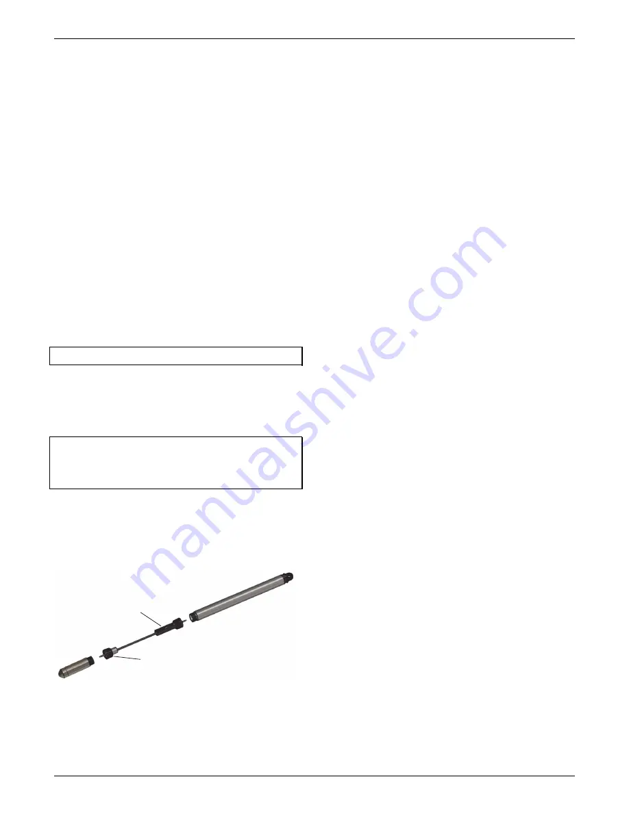
Connect the logger components.

 Connect the top end to 

the sensor end with the water level logger cable as shown 
below. The end of the cable with the longer housing 
connects to the top end as shown below.


3.


Download the app. 

Download HOBOconnect to a phone or 

tablet from the App Store® or Google Play™ or download 
the app to a Windows computer from 
www.onsetcomp.com/products/software/hoboconnect.


4.


Open the app.

 Enable Bluetooth in your phone or tablet’s 

device settings if prompted.


5.


Determine the logger is within range. 

Tap Devices. The 

logger should appear in the list of devices (note that the 
serial number shown in the app is for the top end of the 
logger). If the logger does not appear, make sure it is within 
range of your device. Sensor readings are displayed as “--“ 
when the logger is stopped.


6.


Deploy the logger if ready. 

If you are ready to deploy the 

logger, place it in the deployment location (see 

Deploying 

the Logger

 for deployment guidelines). Otherwise, skip 

deployment and complete the following steps as a test.


7.


Connect to the logger

. Tap the logger tile in the app to 

connect to the logger. Tips for connecting:


Make sure the top end of the logger is within range of 

your mobile device or computer. The range for successful 
wireless communication is approximately 30.5 m (100 ft) 
with full line-of-sight. 


If your device can connect to the logger intermittently or 

loses its connection, move closer to the top end of the 
logger, within sight if possible. 


If the logger appears in the app, but you cannot connect 
to it or if you are experiencing persistent connection 
problems, close the app and then power down your 
device to force the previous Bluetooth connection to 
close. 

Configuring the Logger 

Use the HOBOconnect app to set up the logger, including 
selecting the logging options, configuring alarms, and other 
settings. These steps provide an overview. For complete details, 
see the HOBOconnect User’s Guide. 

Note:

 Edit only the settings you want to change. If you do not 

edit a setting, the logger uses the current setting. 

1.


Tap Devices and then tap the logger tile to connect to the 
logger. 

2.


Tap Configure & Start to configure the logger. 

3.


Tap Name and type a name for the logger. If you do not 
enter a name, the app uses logger serial number as the 
name. 

4.


Tap Group to add the logger to a group (optional). 

5.


Tap Logging Interval and choose how frequently the logger 
records data when not in burst logging mode (see 

Burst 

Logging

). When selecting a logging interval, keep in mind 

that data offload time is proportional to the amount of data 
logged. The faster the logging interval, the more data that 
must be offloaded and the longer it will take. 

Multi-Rate Logging. You can set a total of 8 logging 
segments. After tapping Logging Interval and entering a rate 
for Segment 1, tap Add to set up additional logging 
segments. For each segment, enter the logging interval and 
select the number of samples that will be recorded for the 
selected rate. You do not need to enter the number of 
samples for the last segment because the logger logs at that 
rate until it stops.  

Note:

 If you configure an alarm, the logger uses the logging 

interval you select as the interval at which to check for alarm 
conditions (alarms are not available if burst logging is 
configured). See Setting up Alarms for more details. 

6.


Tap Start Logging and select when logging begins: 

Plug this portion of the cable 
with the longer housing into 
the top end and screw to 
tighten (hand tight) 

Plug this portion of the cable with the 
smaller housing into the sensor end and 
screw to tighten (hand tight) 

Summary of Contents for MX2001-0 Series

Page 1: ... 0 02 kPa 0 003 psi 0 21 cm 0 007 ft water Pressure Response Time 90 1 second at a stable temperature Pressure Absolute and Water Level Measurements MX2001 02 SS S Operation Range 0 to 400 kPa 0 to 58 psia approximately 0 to 30 6 m 0 to 100 ft of water depth at sea level or 0 to 33 6 m 0 to 111 ft of water at 3 000 m 10 000 ft of altitude Factory Calibrated Range 69 to 400 kPa 10 to 58 psia 0 to 4...

Page 2: ... 1 C at 25 C 0 18 F at 77 F see Plot A Response Time 90 5 minutes in water typical Stability Drift 0 1 C 0 18 F per year Logger Operating Range 20 to 50 C 4 to 122 F Radio Power 1 mW 0 dBm Transmission Range Approximately 30 5 m 100 ft line of sight Wireless Data Standard Bluetooth Low Energy Bluetooth Smart Logging Rate 1 second to 18 hours Logging Modes Fixed interval multiple intervals with up ...

Page 3: ... to achieve full temperature compensation of the pressure sensor There can be up to 0 5 of additional error due to rapid temperature changes Measurement accuracy also depends on temperature response time Note Read all the directions in the Deploying a Logger section before deploying the logger Logger Components and Operation Disassembled top end The MX water level logger consists of a top end and ...

Page 4: ...layed as when the logger is stopped 6 Deploy the logger if ready If you are ready to deploy the logger place it in the deployment location see Deploying the Logger for deployment guidelines Otherwise skip deployment and complete the following steps as a test 7 Connect to the logger Tap the logger tile in the app to connect to the logger Tips for connecting Make sure the top end of the logger is wi...

Page 5: ...he current water level when the logger starts logging make sure the sensor is in position when logging starts Make this reading as accurate as possible since this reading is used to calibrate the water level data and adjust it to your reference See section 5 starting on page 7 for information on how to measure and enter the reference water level The logger must be logging for you to enter the refe...

Page 6: ...grommets are available at www onsetcomp com part number GROMMET 5 To install the grommet with the logger 1 Drill two 3 mm or 1 8 inch holes on opposite sides of the well cap for cross ventilation The holes should be just above the top of the grommet when installed as shown 2 Install the grommet with the upper ring sitting on top of the well as shown 3 Install the well cap on top of the well refer ...

Page 7: ...the top end unit in direct sun as that can lead to more rapid temperature swings which can lead to more measurement error and possibly hurt logger reliability To deploy the logger 1 Make sure the top end is connected to the sensor end with the water level logger cable as described in Getting Started with the Logger 2 Attach any small parts such as bolts with nuts before you go into the field so yo...

Page 8: ... alarm is set to 85 F and the duration is set to 30 minutes then the alarm will trip once the sensor readings have been above 85 F for a total of 30 minutes since the logger was configured Consecutive The alarm trips once the sensor reading is out of the acceptable range continuously for the selected duration For example the high alarm is set to 85 F and the duration is set to 30 minutes then the ...

Page 9: ... Logger Events for details on plotting and viewing the event Statistics Logging During fixed logging the logger records data for enabled sensors and or selected statistics at the selected logging interval Statistics are calculated at a sampling rate you specify with the results for the sampling period recorded at each logging interval You can log the following statistics for each sensor The maximu...

Page 10: ...wnloads data to the phone tablet or computer 3 Once the download is complete tap Done to return to the previous page or tap Export and Share to save the file in the specified format 4 When the export file has successfully been created tap Done to return to the previous page or tap Share to use your device s usual modes of sharing You can also upload data automatically to HOBOlink Onset s cloud sof...

Page 11: ...All pressure sensors drift over time The drift for the pressure sensors and electronics in the logger is less than 0 5 FS worst case per year In most applications drift is not a significant source of error because the offset created by any drift is zeroed out when you enter the reference water level in the app at the beginning of each deployment In effect you are re zeroing the sensor each time yo...

Page 12: ...rcuit board is normal when the batteries are installed Reinsert the board 6 Inspect the gore vent on the end cap to make sure it is not damaged Contact Onset or an Onset distributor if you need a replacement vent 7 Inspect the O rings and the mating surface on the logger for any damage clean off any debris and re lubricate the O rings with the grease You can leave the O rings on the end cap during...

Page 13: ...cations not expressly approved by the party responsible for compliance could void the user s authority to operate this equipment Industry Canada Statements This device complies with Industry Canada license exempt RSS standard s Operation is subject to the following two conditions 1 this device may not cause interference and 2 this device must accept any interference including interference that may...

Reviews: