
RSM-WSB(RED)-AS
AUDIOVISUAL WIRELESS WALL SOUNDER
GENERAL DESCRIPTION
The audiovisual wireless wall sounder is an output device that combines together acoustic and visual signaling features performed in
case of fire or emergency situations.
This device is activated by a specific command from the control panel sent through a wire-to-wireless translator module and one or
more possible wireless area expansion modules (known, also, as expander devices).
The communication between the sounder-beacon and the translator / expander modules is wireless via the “Sagittarius” bidirectional
protocol.
This device allows the installer to choose among five different tones and to regulate its output volume setting; incorporated beacon’s
flash rate and light intensity are fixed.
Device Status
Green LED
Red LED
Power up
1 second green, then 0.5 second red for 4 times
Programming and linking to the system
Blinking until linking and programming
is completed
Program - link failure
-
Continuously on
Normal mode
-
-
Main battery fault (low level)
-
Blinking
(0.1 second on and 5 seconds off)
Secondary battery fault (low level)
Blinking
(0.1 second on and 5 seconds off)
-
Both batteries fault
Sequential bicolor blinking
(0.1 second on and 5 seconds off )
Table 1
DEVICE’S POWER SUPPLY AND LINKING
The linking operation permits the configuration of the sounder-beacon device on the translator module.
The linking operation described below does not change if made directly from the
translator module or from the Wirelex PC configura-
tion program.
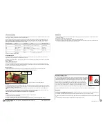
1) Move the “link-program” switch to position ON (picture 1).
2) Insert the secondary battery into its housing (picture 1),
with the poles correctly oriented as indicated on the PCB
.
3) Insert the primary battery into its housing (picture 1),
with the poles correctly oriented as indicated on the PCB
.
The visual LED indicator switches on accordingly (see “Power up” in table 1).
Ensure that both battery polarities are correct!!!
4) When the translator (by itself or piloted by the Wirelex) is searching for a new device for linking, move the “link-program” switch to
position 1 in order to initiate communication with the translator module; the visual LED indicator switches on accordingly (see
“Programming and linking to the system” in table 1).
IMPORTANT NOTE!
Programming is considered to be completed successfully only if there is an indication of programming success on the translator or on
the window of the Wirelex program.
If the linking and programming operation fails, check if mistakes were made with the translator
or the Wirelex, remove the batteries,
switch over alternatively the ON / 1 switch a few times in order to discharge the internal capacitor and then start again from point 1)
re-performing the linking procedure.
SOUNDER VISUAL LED INDICATOR
This device is equipped with a bi-colour LED (red/green) that provides visual indication for functional conditions and battery levels as
indicated in table 1. The indicator is positioned on the device’s PCB (picture 1).
* Ideal operating range: may
vary consistently according to
environmental conditions.
** When a low battery condition is
indicated, both, main and
secondary, batteries must be
changed altogether.
*** This lifespan value refers to the
device being set with a message
transmission period of 12 se-
conds; tests are not considered in
this estimation.
**** Type A for indoor use only.
1
2
COMMUNICATION QUALITY ASSESSMENT
It is possible to assess the wireless communication quality of this device with the system by using an in-built testing feature.
After a successful linking operation, by switching over the “link-program” switch on the ON position, the LED indicator will start blink-
ing according to table 2.
Always remember to reposition the switch to 1 after the assessment operation: device will NOT work operatively while the
switch is positioned on the ON position.
Table 2
HOCHIKI EUROPE (UK) LTD
, Grosvenor Road - Gillingham Business Park - Gillingham -
Kent ME8 0SA - U.K.
www.hochikieurope.com
L20-SGRSV-6100 (v1.1)
TECHNICAL SPECIFICATIONS
Operating frequency
916 MHz
Communication range with translator or expander *
100 m (in open space)
Max radiated power
5 dBm (3 mW)
Radio signal’s modulation type
FSK
Operating frequency channels
6
Main and secondary battery type
CR123A (3 V & 1.2 Ah)
Estimated battery life
**
>3 years
; remains operational for up to
60 days
from first
appearance of the low battery warning ***
Alarm current
100 mA
Operating temperature
-10 °C - +55 °C
Max tolerated humidity (no condensing)
95% RH
Ingress protection rating
IP 21C ****
Sound output volume (selectable)
between 76 dBa and 95 dBa at max volume depending upon
angle and tone selection
Beacon flash rate
1 Hz
Beacon flash light intensity
> 1 Cd
Required programming software
“Wirelex-Fire” revision 5.1.3 and successive
SOUNDER DEVICE REMOVAL FROM THE WALL BASE
In order to remove the sounder device from the wall base, the opening
key must be inserted into the two holes present on the base; hold only
the base firmly with one hand and insert and push the key into its holes
with the other, until the device unblocks. During this operation be careful
not to break the two pins of the key and not to drop the device on the
floor.
Picture 2 - Sounder device
removal from the wall base
KEY TO REMOVE
THE SOUNDER
DEVICE FROM ITS
WALL BASE
DEVICE PLACEMENT
For specific information regarding detector and device’s spacing, placement and special applica-
tions refer to your specific national standards.
It is strongly advised to mount the device as far as possible from metal objects, metal doors,
metal window openings, etc. as well as cable conductors, cables (especially from computers),
otherwise the operating distance may greatly drop. The device should not be installed near
electronic devices and computer equipment that can interfere with the reception’s quality.
1) Select the position of the device before installing it.
Verify, from that position, that the
communication between the device and the translator or the expander is correctly estab-
lished and working (see the COMMUNICATION QUALITY ASSESSMENT paragraph).
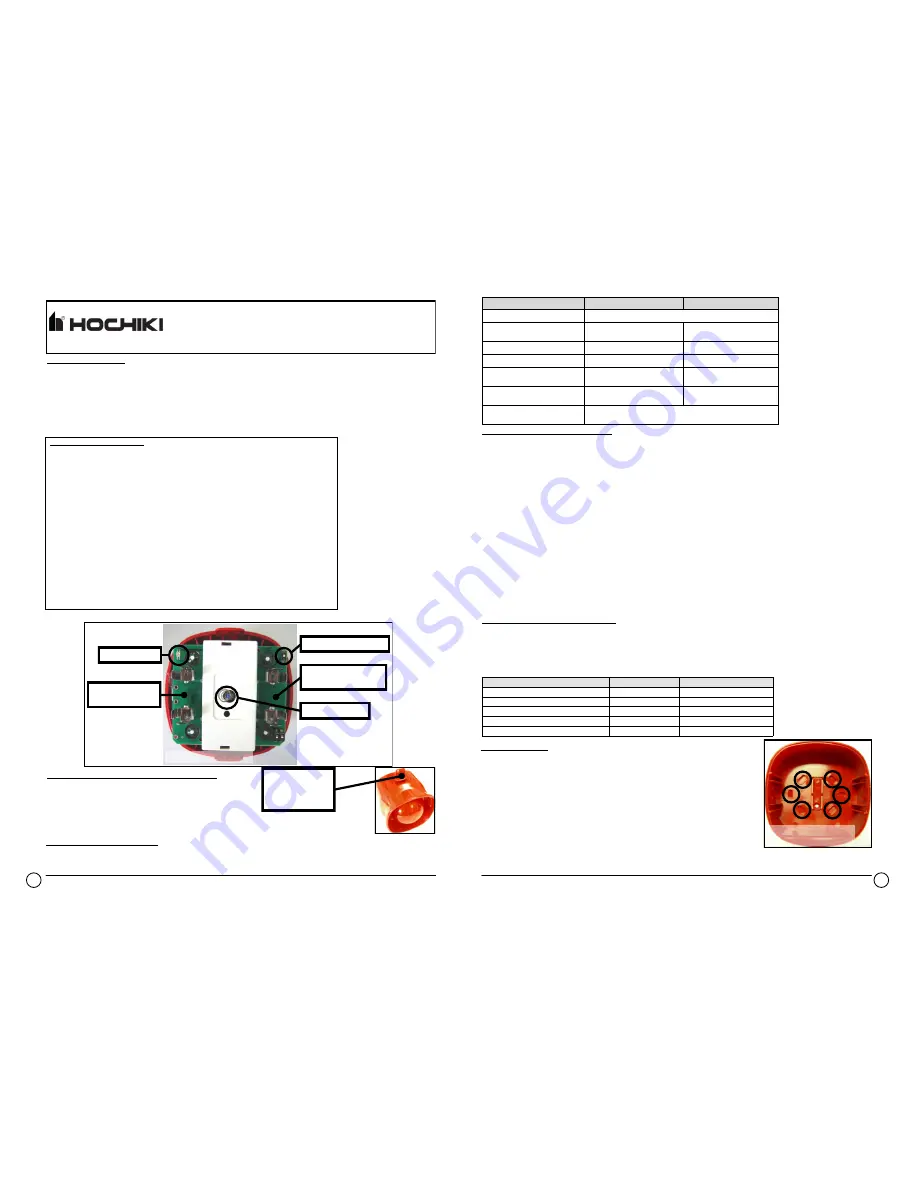
2) Install the wall base in the selected position with the provided screws (picture 3).
3) Set the device’s tone and output volume; see the following paragraphs.
4) Test the sounder-beacon (see the following paragraphs), then install securely the sounder-beacon device onto the fixed wall box.
Picture 3 - Wall fixing screw
entry points on the wall base
Picture 1 - View of the PCB
LED INDICATOR
PRIMARY BATTERY
LODGEMENT
LINK-PROGRAM SWITCH
SECONDARY BATTERY
LODGEMENT
TAMPER SWITCH
Communication quality
Assessment
Device’s indication
No communication
Fail
Two red blinks
Communication quality: 0 dB - 10 dB (Mark 2)
Poor
One red blink
Communication quality: 10 dB - 20 dB (Mark 3)
Medium-low
One green blink
Communication quality: 20 dB - 30 dB (Mark 4)
Good
Two green blinks
Communication quality: > 30 dB (Mark 5)
Excellent
Two green blinks


