


2
Mode Jumper Diagram Figure 1
NON-Heat Pump Applications
For
NON
-Heat Pump System applications, the jumper tab
should be in the
"DA"
position as shown in Figure 1 for proper
operation.
NOTE:
If the jumper tab is in the "RA" position for NON-
Heat Pump applications, the condenser fan motor will operate at
full speed and will not modulate.
A selectable span of 25ºF or 30ºF is available (see
Figure 1
).
The 25ºF span is recommended for high efficiency units while the
30ºF span is recommended for older lower efficiency units.
The Range Adjust potentiometer provides 50ºF-80ºF up to 70ºF-
100ºF for the 30ºF span. The 25ºF span provides for adjustments
from 55ºF-80ºF up to 75ºF-100ºF. Markings are in 5ºF increments.
Typically TXV devices should be set at full CCW or at the second
mark. Orifice or Cap Tube devices should be set at the 4th or full
CW markings. These positions should provide adequate control of
head pressure for the specific device being used. The lower range
adjust positions will allow control to a lower ambient. Conversely,
the higher range adjust positions will provide control only to a higher
ambient. Factory Range Adjustment is set at 50ºF-80ºF.
CAUTION: It is not recommended that the range adjust be set
to satisfy a selected head pressure. These various range adjustments
are provided to ensure proper ambient control when the system is
properly charged (no vapor in the sight glass), filters and coils are
clean, and an air flow of 400 cfm/ton is available for delivery in the
HVAC system. In refrigeration application, consult factory or see
Engineering Bulletin for “Low Ambient Refrigeration Applications.”
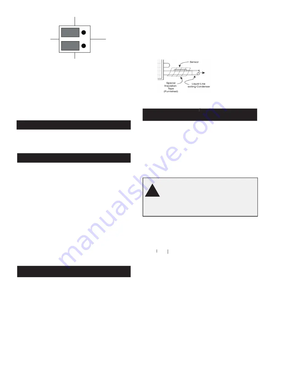
Liquid Line Sensor
• Install Sensor(s) to the top of liquid line where the line exits the
condenser coil (refer to
Figure 2
). If two compressors (circuits)
are used, a second Sensor is required for the second refrigerant
circuit. (Part Number 100-0017-001.)
• Use the special tape provided to secure the Sensor to the liquid
line. Stretch the tape slightly, as you wrap the tape around the
sensor and liquid line. Use all the tape, lapping the Sensor.
• Firm, mechanically clean, contact is required between the metal
tab of the Sensor and the liquid line. When using one sensor,
always use the control's
S1
and
COM
terminals.
•
DO NOT
use tie wraps or hose clamps to secure sensor to
liquid line. Sensor element will break.
• Connect the Sensor(s) wires to the Sensor input terminals.
• Additional insulation of the taped sensor and adjacent refrigerant
line back to condenser header is required in extremely cold ambients
(+20º F).
������������������
�������������������
���������������������
�����������������������
���������������
Sensor Diagram Figure 2
1
Checkout Procedure
Step 1
With power disconnected and the Controller wired:
1.
Measure the ohms across the Control's terminals “#1” and
“#2” using an ohm meter.
2.
For single condenser applications; if you read 1 ohm or less
(115V AC operating voltage), or 5 ohms or less (208V AC or
greater operating voltage), the controller is improperly wired.
CAUTION
Correct wiring error(s). Do not apply power if
incorrect ohm values were measured during para-
graph 2, above. (The load is shorted; applying power
will destroy the controller.)
Step 2
With the compressor disabled, set thermostat for cooling
demand and apply voltage to the unit. Condenser fan will
start if liquid line temperature is 3º above the low ºF value
selected using
selected
selected
the Span jumper and Range Adjuat pot.
using
using
1.
Monitor liquid line temperature (°F) and condenser motor
voltage and current.
2.
Verify that the motor is operating properly for temperature
sensed. Depending on the Range Adjust position, when the
sensor temperature at “start up” is:
a.
Below Selected Span and Range Minimum,
depending on where the range adjust is set, the motor(s)
will not start.
b.
Within Selected Span and Range,
the motor(s) will
start at full speed for a few seconds and immediately
modulate to a reduced speed proportional to the tempera-
ture sensed when the temperature is 3
°
F
above the low end
of the
range adjust.
........................................................................ .
Continued on page 4
�
��
��
����
��
���
���
816-10DH Span
Range Adjust Pot
Sensor Installation


