- 10 -
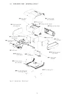
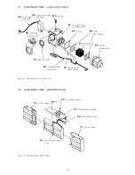
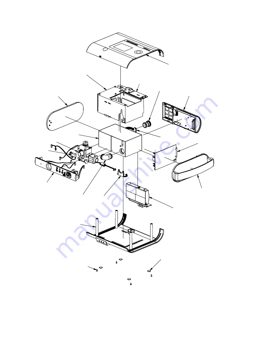
4.3 EXPLODED VIEW - GENERAL LAYOUT
Figure 5: Exploded view - General layout
A1
Front panel
A2
Air outlet with
flow element
A4
Side housing part
without handle
A3
Blower Box
A5
Inner frame
complete
A6
Housing upper
part, complete
A17
Interior wall
A7
Bellows air inlet straight
A8
Back part assembled
A9
PCB,
controller
A10
Side housing part
with handle
A11
Battery pack
complete
A15
Cover,
check valve
A16
Bellows air
outlet, angled
A14
Housing lower
part, complete
A13
4x Lens head screw
for housing (M3 x 8)
A12
4x Housing foot
C6
Control valve
with cable
K10
Motor cable


