background image

- 16 -

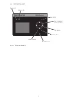
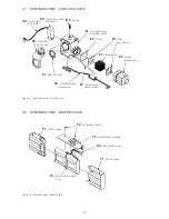
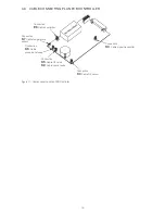
5  IMPORTANT COMPONENTS

The TRENDvent ventilator comprises the following components:


Blower


PCB, DC-communication


Sensors / valves (compressed air distribution)


Power supply


PCB Controller (control and operating unit)


Interfaces

5.1  BLOCK DIAGRAMS

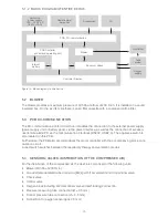
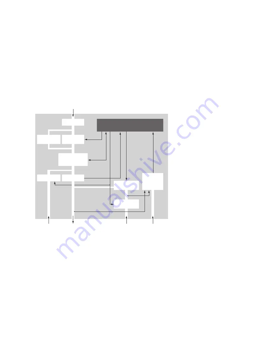
5.1.1  BLOCK DIAGRAM OF COMPRESSED AIR DISTRIBUTION

Proportional

valve

Pressure sen-

sors/excess

Pressure

switch

Air inlet

Air outlet

Blower

Switch 

Filter

Control unit

O2 valve

Check

valve

Flow sensor

Oxygen

connection

Pressure

measuring tube

connection

Control tube

connection

Control

valve

Figure 13: Block diagram of compressed air distribution

Summary of Contents for TRENDvent

Page 1: ...Service Manual Ventilator TRENDvent ...

Page 2: ...omponents 16 5 1 Block diagrams 16 5 1 1 Block diagram of compressed air distribution 16 5 1 2 Block diagram of entire device 17 5 2 Blower 17 5 3 PCB DC communication 17 5 4 Sensors Valves distribution of the compressed air 17 5 5 Power supply 18 5 6 PCB controller Control and operating unit 18 5 7 Operating unit Display 18 5 8 Interfaces 18 6 Servicing 19 6 1 Preliminary steps 19 6 1 1 Tools and...

Page 3: ...7 8 2 Tightness test 27 8 3 O2 valve test 28 8 4 Battery test 29 8 5 Setting the device back to factory settings 29 8 6 Check the electrical safety of the external power supply 30 9 Final works 30 10 Maintenance kits spare part list 31 10 1 Maintenance kits 31 10 2 Spare part list 32 11 Disposal 34 11 1 Device and components 34 11 2 Packaging 34 11 3 Batteries 34 11 4 Oxygen sensor 34 12 Shipping ...

Page 4: ...s connected the internal battery is charged electrical power is still applied to the device Repair and maintenance tasks may only be carried out by suitably qualified authorized and competent personal Oxygen sensors contain a caustic liquid Avoid skin or eye contact if there is a sensor leak For oxygen sensors no adjustment or repair work is required Components carrying oxygen must not come into c...

Page 5: ...ing the internal batteries 1 Changing the battery pack without PCB or changing the battery pack with PCB Safety related check Documentation 22 6 30 Every 3 years after last change of the internal batteries Maintenance kit 2a or 2b Changing the internal batteries Changing the battery pack without PCB or changing the battery pack 22 Every 15000 h blower run time or every 5 years or displaying in the...

Page 6: ...on 3 4 on page 6 Checking the electrical safety of the power supply see section 8 6 on page 30 Final work section 9 on page 30 Packaging of the device according to the packing instructions in section 12 2 1 on page 35 Shipping according to the shipping instructions in section 12 2 2 on page 35 3 3 HYGIENIC PREPARATION During preparation preparation on changing patients as well as preparation after...

Page 7: ... humidifier Oxygen sensor cable connection jack 2 5 mm Display Operating unit Unlocking button for humidifier Contact sockets for humidifier G2 Control tube connection ø 4 5 mm G3 Pressure measuring tube connection ø 3 5 mm G4 Oxygen connection G5 Oxygen output Handle Figure 1 Front view of device ...

Page 8: ...d coarse filter detachable Tube system switch Sign for power supply DC 24V 5A Mains socket Com Service connection RS232 interface RJ11 6 4 PC connection USB interface Typ B Remote alarm LED Remote alarm connection RJ10 4 4 Figure 2 Rear view of device G7 Fine filter Figure 3 Holder filter cassette ...

Page 9: ... 9 4 2 OPERATING UNIT Battery LED esc button Touch wheel with 4 cursor buttons OK button Heating button ON OFF button Alarm button Power LED Figure 4 Operating unit elements ...

Page 10: ...rame complete A6 Housing upper part complete A17 Interior wall A7 Bellows air inlet straight A8 Back part assembled A9 PCB controller A10 Side housing part with handle A11 Battery pack complete A15 Cover check valve A16 Bellows air outlet angled A14 Housing lower part complete A13 4x Lens head screw for housing M3 x 8 A12 4x Housing foot C6 Control valve with cable K10 Motor cable ...

Page 11: ... PART Figure 6 Exploded view Housing upper part B1 Label band K1 Ribbon cable operation panel K2 Ribbon cable display B2 Operation panel B3 Seal operation panel B4 Display B5 3x Screws M2x3 B7 8x Hexagonal nuts M2 5 B6 Housing upper part ...

Page 12: ... Front panel C5 O2 connector C3 O2 block K3 Signal transmitter cable K4 Cable O2 sensor K5 O2 valve cable C4 O2 valve with cable D1 PCB DC communication D2 Back part D3 Holder for filter cassette D4 Filter cassette D10 Coarse filter D5 Cover for connectors D6 DC port D7 Main switch D8 Seal back wall D9 4x Lens head screw 2 2x6 5 C6 Control valve With cable K9 Control valve cable ...

Page 13: ...0 Spring E1 Air outlet without humidifier cable E2 O ring E3 Seal flow element E5 Holder flow element E4 Flow element E6 Humidifier cable assembled F1 Half of casing F1 Half of casing F2 2x Screws 2 2x6 5 F3 PCB Battery charging F4 Internal battery pack 1 set E7 Seal air outlet E8 Humidifier unlock key K8 Cable battery pack K7 Temperature sensor cable K6 Proportional valve cable ...

Page 14: ...able humidifier Connection K7 Cable temperature sensor Connection K6 Cable proportional valve Connection K5 Cable O2 valve K9 Cable control valve Connection K4 Cable O2 sensor Connection K3 Cable signal transmitter Figure 11 Cable connection plan PCB Controller ...

Page 15: ...1 Front panel Sinter element View A A E5 Holder flow element E9 Proportional valve A9 PCB Controller A16 Bellows air outlet C6 Control valve View B B blue1 brown red1 green grey white black no color no color 1 incl sinter element Figure 12 Tube connecting plan ...

Page 16: ... and operating unit Interfaces 5 1 BLOCK DIAGRAMS 5 1 1 BLOCK DIAGRAM OF COMPRESSED AIR DISTRIBUTION Proportional valve Pressure sen sors excess Pressure switch Air inlet Air outlet Blower Switch Filter Control unit O2 valve Check valve Flow sensor Oxygen connection Pressure measuring tube connection Control tube connection Control valve Figure 13 Block diagram of compressed air distribution ...

Page 17: ...ly unit or battery pack via the power interface as well as the connection of accesso ries remote alarm PC via the communication interfaces RS232 USB2 0 The appliance switch is also located on this PCB Furthermore the PCB also accommodates the motor controller with the accompanying block com mutation circuit A reed switch switches between the respiratory therapy and ventilation modes 5 4 SENSORS VA...

Page 18: ...and cur rent for acoustic and visual alarms and the generation of supply voltage 5 7 OPERATING UNIT DISPLAY The operating unit is made of float glass and is 202 x 110 mm in size The material is approx 3 mm thick All elements are described in Figure 4 on page 9 The display is 81 x 61 mm in size and has a resolution of 320 x 240 pixels 5 8 INTERFACES The device has an USB interface for connection to...

Page 19: ...w sensor calibration art no 0000 4946 Adapter for oxygen connection straight art no 4100 0104 RS232 connection cable Airflow resistor 7 mm art no 0000 7305 Blind plug APM art no 0000 4831 PC with following system requirements minimum requirements MS Windows XP Vista or 7 AMD Athlon Pentium Class x86 operating frequency 700 MHz 512 MB RAM recommended at least 400 MB free hard disc space Microsoft N...

Page 20: ...nd disinfected Before assembly ensure that the affected areas are sufficiently dry 1 Switch off the device using the main switch and disconnect it from the mains power as well as all connected components e g humidifier 2 Remove the filter cassette holder D3 3 Place the device with the upper side on a soft surface 4 If the HOFFRICHTER warranty seal is still in place remove it 5 Unscrew the four scr...

Page 21: ...ube on the pressure switch and air outlet E1 Tubes on the control valve C6 6 5 CHECK THE CABLES AND CONNECTIONS Check every connecting and supply cable for correct seating and signs of damage If necessary correct or replace Ribbon cable operation panel K1 Ribbon cable display K2 Cable signal transmitter K3 Cable oxygen sensor K4 Cable oxygen valve K5 Cable proportional valve K6 Ribbon cable temper...

Page 22: ... see section section 8 4 after assembling the device 6 8 CHANGING THE FILTERS 1 Pull the filter cassette holder D3 from the device 2 Slide the filter cassette out from the filter cassette holder D4 3 Remove the coarse filter black D10 4 Remove the fine filter white G7 5 Insert a new coarse filter followed by a new fine filter into the filter cassette 6 9 EXCHANGING THE BLOWER BOX The blower box is...

Page 23: ...nnection tube no color onto the blower box accord ing to the tube connecting plan see Figure 12 on page 15 Fasten the O2 connection tube with the 71 mm cable tie Maintenance kit 5 Cut off the protruding end section with a side cutter 17 Tie up the signal transmitter cable K3 proportional valve cable K6 and control valve cable K9 on the air outlet s right hand side with a cable tie 71 mm Maintenanc...

Page 24: ...k valve Ensure that the fastening tabs on both sides snap in audi bly and that the interior wall A17 sits behind the cover for the check valve It should also be ensured that the cover fit exactly onto the slot of the bellows A7 5 Fit the battery pack and connect the battery pack PCB F3 to the controller PCB A9 6 Insert both lateral housing parts A4 A10 Ensure that they sit correctly in the guides ...

Page 25: ...CHECKING THE STATUS SCREEN FOR ERRORS When the device is started it carries out a self test If any errors are detected the status screen is automatically displayed Faulty parameters will be displayed by ERROR Possible errors must first be corrected before the device can be used 7 5 CHECKING THE DATE AND TIME Switch to the comfort screen and check the date and time If necessary correct the setting ...

Page 26: ...istor 7 mm Flow sensor Figure 15 Measurement setup flow sensor calibration 8 1 2 MANUAL FLOW SENSOR CALIBRATION 1 Connect the flow sensor airflow resistor adapter and TRENDvent see Figure 15 on page 26 2 Activate the Clinic mode 3 Activate the Service screen using the or cursor key 4 Select Flow sensor calibration using the cursor key or touch wheel 5 Press the OK button 6 Enter the PIN code 1302 ...

Page 27: ...stem with the blind plug APM art no 0000 4831 2 Connect the short tube of the blind plug APM to the control tube connection and the long tube to the pressure measuring tube connection 3 Connect the device to the mains power 4 Switch the device on 5 Activate the Clinic mode 6 Activate the Service screen using the or cursor key 7 Select Tightness test using the cursor key or touch wheel 8 Press the ...

Page 28: ...er into the oxygen connection Only the O2 connection adapter supplied may be used to connect oxygen Otherwise there is a risk that the back stop in the connection is damaged Fats or oils must not be used as lubricants in the area around the O2 connection There is a risk for fire and explosion 4 Switch the device on 5 Activate the Clinic mode 6 Activate the Service screen using the or cursor key 7 ...

Page 29: ...progress of the battery test as a percentage After the 2nd phase has ended the capacity of the battery is displayed If the capacity is 80 the test is considered to be passed If the capacity is lower or the message ERROR is displayed in the status screen both batteries or the entire battery pack must be replaced 8 5 SETTING THE DEVICE BACK TO FACTORY SETTINGS The device s standard factory values ca...

Page 30: ... standard The leakage currents should be determined by direct mea surement The ventilation system should be tested with a BF application part according to protection class II The accompanying protection class II power supply is tested in the system Any faults in the power supply are detected in the test of the entire system according to protection class II Device leakage current The device leakage...

Page 31: ...Internal rechargeable battery pack Li Ion without PCB battery changing and housing battery test necessary Table 4 Maintenance kit 2a or Maintenance kit 2b art no 0001 4987 Every 2 or 3 years Quantity Designation 1 Maintenance kit 1 1 set Internal rechargeaable battery pack with housing and PCB battery charging Table 5 Maintenance kit 2b Maintenance kit 5 art no 0001 4986 After 15000 h blower runnn...

Page 32: ...101 A15 Cover check valve 4210 1009 A16 Bellows air outlet angled with cable tie 0001 4146 B1 Label band TRENDvent HOFFRICHTER 2200 0098 B2 Operation panel with sealings and nuts 0001 4145 B3 Seal operation panel 179x1 4 B4 Display 1520 0018 B5 3x screws M2x3 DIN 7985 B6 Housing upper part 0001 4102 C1 Front panel without O2 block 0001 4104 C2 Piezo signal transmitter with PCB and cable 0001 4118 ...

Page 33: ...cable 24 pol for operation panel 3220 0089 Cable flow calibration assembled 0001 4112 Sinter element 4100 0173 Tube set inner with tube connecting plan 0001 4108 Buchse für Sauerstoffanschlusskabel 0001 4136 Rechargeable battery 9 V 1600 0017 Pressure switch 60 mbar 2300 0036 Lithium battery cell CR2032 3 V 1600 0004 Assembly set flow element E4 2x seal E3 holder flow element fastening element E5 ...

Page 34: ... public waste disposal authority 11 2 PACKAGING The packaging can be disposed with the normal household waste 11 3 BATTERIES Batteries must not be disposed of with the household waste They must be disposed of at a local retailer or at a communal collection point 11 4 OXYGEN SENSOR The oxygen sensor must not be disposed of with the household waste It should be disposed of correctly by incineration ...

Page 35: ...ONTAMINATED EQUIPMENT must be visibly placed on the packaging The packaging must be proper and robust and must not be contaminated The box is conscien tiously sealed with packing tape 12 1 3 SHIPPING The delivery note must be on the outside of the equipment packaging Notice on delivery note CAUTION CONTAMINATED EQUIPMENT or CAUTION MRSA CON TAMINATED EQUIPMENT Shipping takes place by appropriate l...

Page 36: ...HOFFRICHTER GmbH Mettenheimer Straße 12 14 19061 Schwerin Germany Phone 49 385 39925 0 Fax 49 385 39925 25 E Mail info hoffrichter de www hoffrichter de TRENDventServiceENG_2012 07 19_06 ...

Reviews: