- 17 -
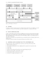
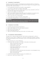
5.1.2 BLOCK DIAGRAM OF ENTIRE DEVICE
Oxygen
supply
Humidifier
Tube
system
Controls / Display
Accessories
PC
Internal
battery
Sensors / Valves
Remote alarm
Nurse call
PCB, DC-communication
Blower
Switching
power supply
100 ... 240 V AC
(-20%, +10%)
PCB Controller
(control and operating unit)
Figure 14: Block diagram of entire device
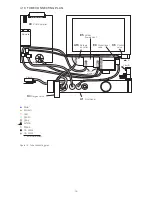
5.2 BLOWER
The blower provides a maximum pressure of 40 hPa at a flow of 200 l/min. It is installed in a sound
insulated box. On the air inlet side there is an air filter cassette with a coarse and a fine filter.
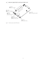
5.3 PCB DC-COMMUNICATION
The DC-communication printed circuit board enables the connection to the external power supply
(power supply unit or battery pack), via the power interface, as well as the connection of accesso-
ries/remote alarm/PC via the communication interfaces (RS232, USB2.0). The appliance switch is
also located on this PCB.
Furthermore, the PCB also accommodates the motor controller with the accompanying block-com-
mutation circuit.
A reed switch switches between the respiratory therapy and ventilation modes.
5.4 SENSORS / VALVES (DISTRIBUTION OF THE COMPRESSED AIR)
For the distribution of the compressed air, the device is composed of the following units:
•
Blower (40 hPa at 200 l/min)
• Air outlet (standardized tube connector [M22]) with flow element and proportional valve
•
Check valve
•
Control valve
•
Oxygen block including 3/2 directional valve and self-locking connection
•
Pressure measuring tube connection (
∅
= 3.5 mm)
•
Control pressure tube connection (
∅
= 4.5 mm)
•
Connection for oxygen sensor (jack 2.5 mm)

