- 24 -
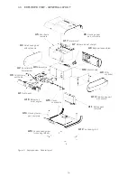
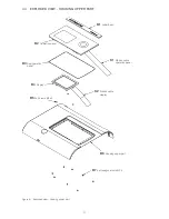
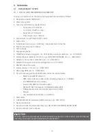
6.10 ASSEMBLING AND CLOSING THE DEVICE
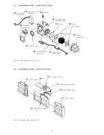
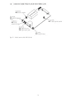
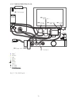
1. Take the housing’s back part (A8) and connect the motor cable (K10) with the DC-communica-
tion PCB (D1).
2. Fit the housing’s back part (A8) into the housing’s upper part (A6).
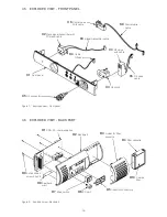
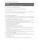
3. Connect the controller PCB (A9) and the back part (A8) with the DC-communication PCB and
position the controller PCB into the corresponding guides in the upper part of the housing (A6).
Check the position and fit of the back part.
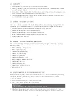
4. Fit the cover for the check valve. Ensure that the fastening tabs on both sides snap in audi-
bly and that the interior wall (A17) sits behind the cover for the check valve. It should also be
ensured that the cover fit exactly onto the slot of the bellows (A7).
5. Fit the battery pack and connect the battery pack PCB (F3) to the controller PCB (A9).
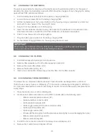
6.
Insert both lateral housing parts (A4 + A10). Ensure that they sit correctly in the guides.
7.
Finally, check that all components and connections fit correctly.
8. Fit the lower part (A14) and securely tighten all four screws (A13). Ensure that none of the
cables and tubes are squeezed.
9.
Insert the filter cassette holder (D3, with new filters) into the back part (A8).

