background image

1

KENNZEICHNUNG DER BEDIENUNGSELE-

10

IDENTIFICACION  DE  COMANDOS
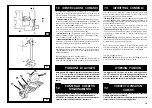
ARBEITS  POSITION

12

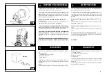
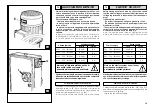
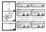
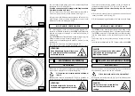
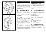
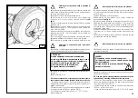
Der bewegliche Ständer mit den Bedienungselementen (Abb. C) 

macht es dem Bediener möglich, den Arbeitsplatz zu wählen, der 

von Fall zu Fall bequemer ist. Auf diesem Ständer befinden sich alle 

zu verwendenden Bedienungselemente, und zwar:

Der Steuergriff (8, Abb. C)

 in der Stellung 

[a]

 hebt dem Spannfut-

tertragearm, in der Stellung 

[b] 

senkt er ihn. In der Stellung 

[c]

 nähert 

er den Werkzeugtrageschlitten und die bewegliche Plattform an das 

Spannfutter an, in der Stellung 

[d] 

entfernt er sie davon.

Hinweis: Um diese Stellungen besser behalten zu können, sollte 

man sich merken, daß auf der Höhe der Stellung c ein Loch im 

Schutz des Steuergriffes vorhanden ist.

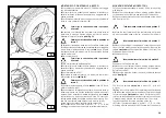
Der Schalter (9, Abb. C)

 nach oben betätigt öffnet die Arme des 

Spannfutters (AUFSPANNEN). Wird er nach unten bewegt, schließt 

er die Arme des Spannfutters (FREIGABE).

Das Kippedal (10, Abb. C) 

macht es möglich, wenn man es in einer 

der beiden Richtungen betätigt, das Spannfutter in der einen oder 

anderen Richtung zu drehen, so wie es durch die Pfeile auf dem 

Pedal angezeigt wird.

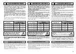
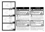
Beide Drehungen können mit zwei Geschwindigkeiten er folgen.

Es  genügt,  den  Wähler  (12,  Abb.  6/B)  in  Pos.  1  für  langsame 

Geschwindigkeit  und  in  Pos.  2  für  schnelle  Geschwindigkeit  zu 

positionieren.

Auf der Reifenmontiermaschine sind außerdem vorhanden:

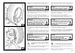
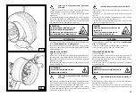
Der Griff (15, Abb. D) 

zum Kippen des Werkzeugtragearms 

(14, Abb. D) 

aus der Arbeitsstellung in die Stellung “außer Betrieb” 

und umgekehrt.

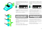
In der Zeichnung (B/8) sind die verschiedenen Arbeitspositionen 

(A, B, C, D) angezeigt, auf die wir bei der Beschreibung der 

Bedienung der Reifenmontiermaschine Bezug nehmen werden. 

Wenn man an den angezeigten Stellen arbeitet, wird der Vor-

gang für den Bediener präziser, schneller und sicherer. 

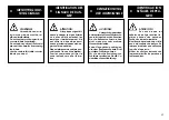
PRUFUNG  AUF  KORREKTEN 

BETRIEB

Bevor man beginnt, mit der Reifenmontiermaschine zu arbeiten, 

sind einige Kontrollen vorzunehmen, um sicherzustellen, daß 

sie korrekt funktioniert.

ACHTUNG:  Für  die  untenstehend  beschriebenen  Kontrollen 

CONTROL  DEL  CORRECTO 

FUNCIONAMIENTO

12

IDENTIFICATION DES COMMANDES

10

La  colonnette  mobile  des  commandes  (fig.  C)  permet  à 

l’opérateur de choisir la position de travail la plus convenable. 

Toutes les commandes sont rassemblées sur cette colonnette, 

à savoir: 

Le manipulateur (8, fig. C)

 en position 

[a]

 il lève le bras porte-

mandrin, en position 

[b]

 l’abaisse, en position 

[c]

 il approche 

le chariot porte-outils et la plate-forme mobile au mandrin, en 

position 

[d]

 il l’éloigne.

Nota:  Pour  mieux  mémoriser  cette  dernière  opération, 

un  trou  a  été  percé  à  la  hauteur  de  la  position 

c

 sur la 

protection du manipulateur.

L’interrupteur (9, fig. C)

  permet  d’ouvrir  les  bras  du  mandrin 

(BLOCAGE) quand il est actionné vers le haut; les bras se fer-

ment (DEBLOCAGE) s’il est actionné vers le bas.

La pédale à balancier (10, fig. C)

 permet la rotation du mandrin 

dans un sens ou dans l’autre, indiqué par les flèches placées 

sur le pédalier.

Les deux rotations peuvent avoir deux vitesses différentes. Il suffit 

de placer le sélecteur (12, fig. B/6) en position 1 pour la rotation 

lente et en position 2 pour la ro0tation rapide du centreur.

Sur le démonte-pneus sont aussi montés:

La poignée (15, Fig. D)

 qui permet de basculer le bras porte-outil 

POSITION  DE  TRAVAIL

Le schéma B/8 indique les différentes positions de travail (A, 

B, C, D) qui sont rappelées au cours des instructions d’utilisa-

tion du démonte-pneus. Travailler dans la position indiquée 

consent une plus grande précision, rapidité et sécurité pour 

CONTROLE   DU  BON FONC-

TIONNEMENT

12

Avant d’utiliser le démonte-pneus il est nécessaire d’effectuer 

plusieurs contrôles de vérification de bon fonctionnement.

ATTENTION: Les opérations suivantes doivent être effectuées 

avec le bras porte-outils en position “hors service”.

La columna móvil de mandos (Fig. C) permite al ope-

rario elegir la posición de trabajo más conveniente. 

En esta columna están concentrados todos los co-

mandos:

-  El  manipulador (8, Fig. C) 

en  posición 

"a"

  eleva  el  brazo 

porta autocentrante; en posición 

"b" 

lo baja; en posición

 "c"


acerca el carro porta-útiles y la peana móvil al autocentrante; 

en posición 

"d" 

lo aleja.

NOTA: Para memorizar mejor esta última operación, en 

el  protector  del  manipulador  hay  un  orificio  en  corre

-

spondencia con la posición

"c"

.

-  El  interruptor  (9,  Fig.  C)

  accionado  hacia  arriba  abre 

los  brazos  del  autocentrante  (BLOQUEA);  accionado 

hacia  abajo  cierra  los  brazos  del  autocentrante  (DES-

BLOQUEA).

- El pedal doble (10, Fig. C)

 permite accionando en uno 

de los dos lados hacer girar el autocentrante en un sen-

tido u otro como indican las flechas de los pedales.

Las  dos  rotaciones  pueden  tener  dos  tipos  de  veloci-

dad.

Colocar  el  conmutador  en  pos.  1  para    la  velocidad 

lenta.

Colocar  el  conmutador  en  pos.  2  para    la  velocidad 

POSICION  DE  TRABAJO

En el esquema B/8 se muestran las diferentes posiciones de 

trabajo (a, b, c, d) que serán más adelante indicadas du-

rante las instrucciones de uso de la desmontadora.

Operar desde las posiciones indicadas permite mayor pre-

cisión, velocidad y seguridad.

Antes de comenzar a utilizar la desmontadora son necesarios 

algunos controles para verificar el correcto funcionamiento.

ATENCIÓN: Las operaciones siguientes deben ser efectuadas 

con el brazo porta útiles en posición de reposo.

10

Summary of Contents for MEGAMOUNT 551

Page 1: ...S MANUAL D INSTALLATION D UTILISATION ET D ENTRETIEN INSTALLATION BEDIENUNG UND WARTUNG MANUAL DE INSTRUCCIONES SMONTAGOMME UNIVERSALE UNIVERSAL TRUCK TYRE CHANGER DEMONTE PNEUS UNIVERSEL UNIVERSELLE LKW REIFENMONTIERGERÄT DESMONTADORA DE NEUMATICOS UNIVERSAL ED 03 06 MEGAMOUNT 551 ...

Page 2: ...nforme a cuanto està previsto en las especificaiones EN 45014 DICHIARAZIONE CE DI CONFORMITA CE DECLARATION OF CONFORMITY DECLARATION DE CONFORMITE CE CE ÜBEREINSTIMMUNG DECLARACION CE DE CONFORMIDAD al quale questa dichiarazione si riferisce E CONFORME ALLE SEGUENTI DIRETTIVE to which declaration refers is IN CONFORMITY WITH THE FOLLOWING DIRECTIVES au quel cette déclaration se rapporte EST CONFO...

Page 3: ...ITION DE TRAVAIL 12 CONTROLE DU BON FONC TIONN 13 UTILISATION 13 1 Blocage de la roue Blocage des jantes en alliage 13 2 Roues tubeless et supersingle Détalonnage Démontage Montage 13 3 Roues à chambre à air Détalonnage Démontage Montage 13 4 Roues avec cercle Détalonnage et démontage Montage 14 ENTRETIEN ORDINAIRE 15 INCONV CAUSES REMEDES 16 MANUTENTION 17 REMISAGE 18 MISE A DECHARGE 1 ALLGEMEINE...

Page 4: ... understand the contents of these operating instruc tions The Manufacturer shall not liable for any injury to persons or damage to things caused by improper use of this machine KEEP THIS MANUAL NEAR THE MACHINE AND CONSULT IT AS Any work however minor on the electric system must be done exclusively by professionally qualified personnel NORME GENERALI DI SICUREZZA 3 L uso dell apparecchiatura è con...

Page 5: ...ung hat Jede Umrüstung oder Änderung der Maschine die vorher nicht vom Hersteller genehmigt worden ist befreit diesen von der Haftung für etwaige Folgeschäden Die Entfernung oder der Aufbruch der Sicherheitsvorrichtungen SICHERHEITSBESTIMMUNGEN 3 2 TECHNISCHE DATEN Alle Arbeiten an der elektrischen Anlage auch kleineren Umfangs dürfen nur von entsprech end geschultem und qualifizier tem Personal v...

Page 6: ...Limita la massima pressione sul circuito oleodinamico salva guardando il buon funzionamento dell impianto 3 Interruttore magnetotermico di protezione del motore pompa situato all interno della centralina elettrica Interviene in caso di surriscaldamento del motore evitandone la bruciatura 4 Valvola di non ritorno sulla linea idraulica di sollevamento del braccio mandrino Evita una possibile discesa...

Page 7: ...nkert 3 ohne Verpackung In der ersten und der zweiten Version muß die Maschine mit einem Gabelstapler befördert werden dessen Gabeln an den in der Abbildung gezeigten Stellen ansetzen Abb A 2 Für die anderen Versionen sind die Angaben des Abschnittes BEWEGEN auf Seite 59 dieses Handbuchs zu beachten Das Versandgewicht der Maschine beträgt 600 kg TRANSPORTE 5 La máquina se puede entregar bajo pedid...

Page 8: ...om 30 95 without condensation Temperature from 0 55 C UNPACKING B 5 A 7 1 7 1 INSTALLATION PLACE LUOGO DI INSTALLAZIONE 2500 mm 2500 mm 1000 mm 700 mm ATTENZIONE Non è consentito l utilizzo della macchina in atmosfera esplosiva ATTENTION The machine must not be operated in explosive atmospheres L area di ingombro massima della macchina è di mm 2240 x 1640 mantenendo una distanza minima da eventual...

Page 9: ...a Las condiciones ambientales de trabajo deben cumplir los siguientes requisitos Humedad relativa del 30 al 95 sin condensa ción ACHTUNG Es ist nicht gestattet die Maschine in explosionsge fährdeten Räumen zu benutzen ATTENTION Il est interdit d utiliser la machine dans un environnement explosif ATENCIÓN No está permitida la utilización de la máquina en atmósfera explosiva Die Maschine benötigt ei...

Page 10: ...20 cm thick with a minimum concrete quality of B25 in accordance with DIN 1045 requirements foundations For your reference see the side drawing as well as the table herebelow If a floor of this type is not available on site fastening points of the specified concrete quality are acceptable Thesurface onwhichtheuniversaltyre changeristobeinstalled must be flat and well levelled in all directions Inc...

Page 11: ...orhandener Bodenneigung Paßstücke oder Keile verwendet werden so sind längere Befestigungsdübel zu verwenden Die Verankerungsschraube in jede Bohrung einsetzen Die Verankerungsschrauben müssen mindestens 125 mm in den Beton hineinragen siehe Abbildung Bei Verwendung von Rädern die schwerer als 1000 kg sind ist es nötig das Reifenmon tiergerät am Boden mittels Verankerungss chrauben zu befestigen L...

Page 12: ... B 7 e verificare che il senso di rotazione del motore della centralina oleodinamica sia quello indicato dalla freccia 6 fig B 6 In caso contrario fare invertire tra loro da personale CONTROLLO SENSO DI ROTAZIONE Before making any electric hook up check to be certain that the mains voltage corresponds to that stamped on the voltage tag attached to the cord near the tyre changer s plug It is absolu...

Page 13: ...erstrom geschützt werden Lesen Sie auf dem Typenschild auf der Maschine die Stromauf nahme ab und prüfen Sie ob das fragliche Stromnetz damit belastet werden kann Jeder Schaden der sich aus der Nichtbeachtung dieser An weisungen ergibt enthebt den Hersteller von jeder Haftung und führt zum Verfall des Garantieanspruchs Arbeiten an der elektrischen Anlage auch kleineren Umfangs müssen unbedingt dur...

Page 14: ...Collane braccialetti abiti non aderenti possono costituire pericolo per chi opera 1 Staffa di sollevamento 2 Braccio porta autocentrante 3 Autocentrante 4 Pedana 8 Manipolatore 9 Interruttore a levetta 10 Pedale a bilanciere 13 Carrello 14 Braccio porta utensile 15 Leva aggancio braccio 17 Disco stallonatore 18 Utensile a becco 22 Griffa di bloccaggio 1 3 2 4 17 18 14 15 13 22 ...

Page 15: ...Hebebügel 2 Spannfuttertragearm 3 Spannfutter 4 Plattform 8 Steuergriff 9 Schalter 10 Kippedal 13 Schlitten 14 Werkzeugtragearm 15 Armhebel 17 Abdrückscheibe 18 Hakenwerkzeug 22 Spannklaue ATTENTION Pendant le travail tenir les mains et les autres parties du corps le plus loin pos sible des parties en mouvement Les colliers bracelets vêtements flottants peuvent constituer un danger pour l opérateu...

Page 16: ... Non utilizzare lo smonta gomme se mancante di una o più targhette di pericolo Non interporre oggetti che ne ostruiscano la visione all opera tore Per eventuali richieste utilizzare il codice indicato nella presente tavola 3005419 3005423 3006037 3005410 3005421 3006038 3005417 3005087 3000962 3000964 3000965 3000961 3000963 3008615 3008614 3008616 3013614 ...

Page 17: ...d any object that could prevent the operator from seeing the labels Use the code in this table to order labels you need ATTENTION Si les plaques signaléti ques de danger sont peu lisibles ou si elles ont été enlevées les remplacer immédiatement Ne pas utiliser le démonte pneus si une ou plusieurs plaques de dan ger sont man quantes Ne pas interposer des objets pou vant cacher la vue à l opérateur ...

Page 18: ...e following pages describing how to use the tyre changer Use of these positions ensures greater precision speed and safety for those using the machine The mobile control centre fig C enables the operator to work at any position around the machine On this mobile control centre the following controls are located The lever 8 fig C which in position a lifts the chuck arm and in position b lowers it in...

Page 19: ...e opération un trou a été percé à la hauteur de la position c sur la protection du manipulateur L interrupteur 9 fig C permet d ouvrir les bras du mandrin BLOCAGE quand il est actionné vers le haut les bras se fer ment DEBLOCAGE s il est actionné vers le bas La pédale à balancier 10 fig C permet la rotation du mandrin dans un sens ou dans l autre indiqué par les flèches placées sur le pédalier Les...

Page 20: ...istruzioni mantenendosi al di fuori del raggio di azione dei vari bracci operanti Move the joystick towards the left c the tool carriage and the mobile platform 13 Fig D should move towards the spindle 3 Fig A move the joystick towards the right d the carriage and platform should move away from the spindle 2 Turn switch lever 9 Fig C towards the top the spindle arms 3 Fig A should open move the le...

Page 21: ...pu lateur vers le bas b le bras porte mandrin doit s abaisser ATTENTION L abaissement du bras porte mandrin créé des points potentiels d écrasement Travailler toujours depuis la position indiquée dans les instructions en se plaçant hors du rayon d action de tous les bras opérationnels ATTENTION Les opérations d ouverture et de fermeture du mandrin créent des points d écrasement potentiels Travaill...

Page 22: ...ettuarla manualmente solo nel caso si sia assolutamente sicuri di riuscire a mantenere in equilibrio la ruota Per ruote pesanti e di grandi dimensioni si DEVE utilizzare un adeguato mezzo di sollevamento 4 Sempre agendo sul manipolatore alzare od abbassare il braccio porta autocentrante fino a centrare il più possibile l autocentrante 3 fig A rispetto al cerchio 5 Con le griffe 22 fig A in posizio...

Page 23: ...onnette mobile de commande ATTENTION Cette opération peut être extrêmement dangereuse Elle doit être effectuée manuellement seulement quand on est absolument sûr de réussir à maintenir la roue en équilibre Dans le cas de roues lourdes et de grandes dimensions IL FAUT utiliser un moyen de levage approprié 4 Toujours à l aide du manipulateur faire monter ou descendre le bras porte mandrin de manière...

Page 24: ...or rims exceeding a diameter of 46 and without a flangr BLOCCAGGIO CERCHI IN LEGA ATTENZIONE Non abbandonare il posto di lavoro con la ruota bloccata sull autocentrante e sollevata da terra LIGHT ALLOY RIM LOCKING The 137 90 clamps especially designed for operating on light alloy rims without damaging them is available upon request The 137 90 clamps are to be inserted bayonet like mounting into th...

Page 25: ... Il est aussi possible d utiliser la pince 138 90 pour jantes en alliage BLOCAGE DES JANTES EN ALLIAGE ATTENTION N abandonnez pas le poste de travail avec la roue bloquée sur le mandrin et soulevée du sol au type de jante voir les figures E 1 E 2 E 3 E 4 E 5 E 6 Sachez que le blocage sur le plateau central est toujours plus sûr N B pour les jantes à gorge bloquer la roue de manière à ce que le cre...

Page 26: ...TENZIONE Non tenere le mani sull utensile quando lo si riporta in posizione di lavoro potrebbero schiacciarsi tra l utensile stesso e la ruota 8 Ruotare l utensile di 180 togliendo il pomolo di bloccaggio Ripetere le operazioni precedentemente descritte ai punti 5 e 6 fino al completo distacco del secondo tallone N B Durante la stallonatura l utensile a becco 18 fig G può essere abbassato in modo ...

Page 27: ... forma que el perfil exterior de la rueda roce el disco destalonador Fig F 5 Hacer girar la rueda y contemporáneamente avanzar con el disco destalonador con breves impulsos siguiendo lo mejor posible el perfil de la llanta 6 Avanzar hasta separar por completo el primer talón Para agilizar la operación con la rueda en movimiento lubricar el talón y el perfil de la llanta con la grasa específica o u...

Page 28: ...tici tubeless può avvenire in due modi 1 Se la ruota non presenta difficoltà di smontaggio proseguire dopo la stallonatura spingendo con il disco stallontore sul fianco interno del pneumatico fino a far uscire i due talloni dal cerchio vedi fig H 2 Se la ruota è del tipo SUPERSINGLE o comunque è partico larmente dura e pertanto non è possibile agire come descritto al punto 1 si rende necessario l ...

Page 29: ...drückt hält bis der Wulst ganz herausgelöst ist Den Werkzeugtragearm in die Position außer Betrieb fahren Das Rad drehen und das Hakenwerkzeug gleichzeitig nach vorne bewegen wobei es zwischen Felge und Wulst einge schoben wird bis es fest am Wulst verankert ist vgl Abb I Die Felge etwa 4 5 cm vom Werkzeug wegbewegen damit vermieden wird daß der Wulst vom Werkzeug rutscht Das Hakenwerkzeug nach au...

Page 30: ...ther the bead breaker disk or the hook tool If the tyre is not problematic use the bead loosener disk If the tyre is very rigid the hook tool must be used MONTAGGIO CON DISCO Agire nel modo seguente 1 Se il cerchio è stato smontato dall autocentrante ribloccarlo come descritto nel paragrafo BLOCCAGGIO DELLA RUOTA 2 Lubrificare i talloni del pneumatico e cerchio con apposita soluzione saponata 3 Se...

Page 31: ...r aufgespannt werden die im Abschnitt RADAUFSPANNEN beschrieben wird 2 Die Reifenwülste und die Felge mit der Seifenlauge schmieren 3 Die Zange am Außenhorn der Felge befestigen und zwar 4 Den Reifen auf die Plattform stellen und das Spannfutter senken dabei ist zu beachten daß die Zange immer an der höchsten Stelle bleibt um den ersten Wulst an der Zange zu befestigen 5 Die Felge mit dem angehakt...

Page 32: ...Posizionare la pedana sotto la verticale della ruota ab 13 Chiudere completamente le griffe dell autocentrante aven do cura di sostenere la ruota per evitarne la caduta 13 Close the arms of the spindle completely Support the wheel to prevent it falling off ATTENZIONE Questa operazione può essere estremamente pericolosa Effettuarla manualmente solo nel caso si sia assolutamente sicuri di riuscire a...

Page 33: ...bb N 9 Das Spannfutter im Uhrzeigersinn um 90 verdrehen bis die Zange in der 9 Uhr Stellung steht 10 Die Abdrückscheibe vorwärts bewegen bis zu 1 2 cm in das Felgenhorn hinein aber immer circa 5 mm Abstand vom Profil halten Die Rotation im Uhrzeigersinn beginnen und sicherstellen daß der zweite Wulst nach einer Rotation von 90 beginnt in das Felgenbett zu rutschen 11 Wenn die Montage beendet ist d...

Page 34: ...utensili in posizione di fuori lavoro traslarlo sul fianco esterno del pneumatico e riagganciarlo in questa posizione 9 Ruotare l utensile di 180 10 Montare la pinza nel punto più in basso ore 6 al di fuori del secondo tallone vedi Fig N Portarsi con la colonnetta mobile in posizione di lavoro D 11 Ruotare l autocentrante in senso orario di circa 90 fino a portare la pinza a ore 9 12 Avanzare con ...

Page 35: ...er Stellung wieder einrasten lassen 9 Das Werkzeug um 180 verdrehen 10 Die Zange an der tiefsten Stelle 6 Uhr Stellung außerhalb des zweiten Wulstes montieren vgl Abb N 11 Das Spannfutter im Uhrzeigersinn um circa 90 drehen bis die Zange in der 9 Uhr Stellung steht 12 Mit den Werkzeug vorfahren bis sein roter Bezugspunkt auf der Achse mit der Außenkante der Felge steht und einen Abstand von 5 mm d...

Page 36: ...t to work position C Portarsi con la colonnetta mobile in posizione di lavoro C 1 Tip the tool carrier arm 14 Fig D to its non working posi tion Move it to the outside plane of the wheel and rehook it in this position 2 Rotate the wheel and at the same time move the hook tool 18 Fig D forward inserting it between rim and bead until it is anchored to the tool 3 Move the rim 4 5 cm from the tool tak...

Page 37: ... läßt bis der Wulst auf das Werkzeug aufgezogen ist 3 Die Felge circa 4 5 cm vom Werkzeug entfernen damit vermieden wird daß der Wulst vom Werkzeug rutscht 4 Das Hakenwerkzeug nach außen fahren bis der rote Bezug spunkt sich in der Nähe der Felgenaußenkante befindet DEMONTAGE Den beweglichen Ständer in die Arbeitsposition C bringen 5 Den Hebel vgl Abb P rechts vom Werkzeug zwischen Felge und Wulst...

Page 38: ...that its red reference dot is about 3 cm inside the rim 13 Insert lever between rim and bead at the right of the tool See Fig Q 14 Press down on the lever and lower the wheel to bring the edge of the rim about 5 cm from the hooked tool Turn the wheel anticlockwise pressing down on lever until the tyre comes completely off the rim ATTENZIONE La fuoriuscita dei talloni dal cerchio causa la caduta de...

Page 39: ... Wulst stecken vgl Abb Q 14 Den Hebel gedrückt halten und das Rad senken bis das Felgenhorn einen Abstand von circa 5 mm vom Hakenwerkzeug hat Dann das Rad im Gegenuhrzeigersinn verdrehen bis der Wulst ganz von der Felge gelöst ist ACHTUNG Wenn der Wulst sich von der Felge löst führt das dazu daß der Reifen hinfällt Immer sicherstellen daß sich niemand im Arbeitsbereich befindet MONTAGE 1 Wenn die...

Page 40: ...co 11 Portare il braccio portautensili in posizione di fuori lavoro traslarlo sul fianco esterno del pneumatico 12 Ruotare l utensile di 180 Portarsi con la colonnetta mobile in posizione di lavoro D Take the mobile control unit to work position D 10 Remove the tool from the tyre 11 Move the tool carrier arm to its non working position Move it to the outside plane of the tyre 12 Turn the tool 180 ...

Page 41: ...g außer Betrieb bringen ihn auf die Außenseite des Reifens verfahren und in dieser Stellung wieder einrasten lassen 12 Das Werkzeug um 180 verdrehen 13 Das Spannfutter verdrehen bis die Ventilöffnung unten steht 6 Uhr Stellung 14 Die bewegliche Plattform 4 Abb A auf die senkrechte Achse des Rades bringen und das Spannfutter senken bis es die Plattform berührt Die Plattform nach außen fahren um Pla...

Page 42: ...o its working posi tion 22 Bring the tool forward until the red reference dot is lined up with the outside edge of the rim and about 5 mm from it 23 Turn the spindle a little clockwise until you can insert the bead guide lever into its seating on the hook tool See Fig V This lever is furnished as an optional 24 Pull back on this lever which will guide the bead into centre well Continue to turn the...

Page 43: ...tt führen wird und die Rotation fortsetzen bis die Montage des Reifens vollendet ist 25 Die Zange entfernen Das Werkzeug herausnehmen indem man das Spannfutter im Gegenuhrzeigersinn dreht und nach außen fährt 28 Wenn der Reifen auf der Plattform steht prüfen daß das Ventil in der Mitte der Öffnung steht Andernfalls das Span nfutter leicht verdrehen um die Position zu verbessern Das Ventil dann mit...

Page 44: ...re sul pneumatico facendo avanzare il disco stallonatore fino a che circa metà del pneumatico non sia uscito dal cerchio vedi Fig K RUOTE CON CERCHIETTO WHEELS WITH SPLIT RING STALLONATURA E SMONTAGGIO BEAD BREAKING AND DEMOUNTING RUOTE CON CERCHIETTO A 3 PEZZI WHEELS WITH 3 PIECE RINGS 1 Bloccare la ruota sull autocentrante come precedentemen te descritto e assicurarsi che la stessa sia sgonfia 2...

Page 45: ...Den Spaltring entfernen 8 Den Werkzeugtragearm 14 Abb D vom Felgenhorn ent fernen Den Sperrkegel ausrasten und den Arm in die Position außer Betrieb heben Den Werkzeugtragearm auf die Radinnenseite bringen 9 Den Hebel 15 Abb D drücken und das Werkzeug um 180 verdrehen bis es automatisch einrastet Den Arm in die Arbe itsstellung senken 10 Das Spannfutter verdrehen und die Abdrückscheibe gleichzeiti...

Page 46: ...has clicked into position on the bar 3 Use the joystick to position the wheel so that the bead breaker disk touches up against outside edge of the centre well rim 4 Turn the spindle and at the same time move the bead breaker disk forward until the split ring is detached Watch out for the O ring 5 Repeat this operation but this time move the disk against the split ring See Fig Z until the locking r...

Page 47: ...t hat Dabei auf das Ventil achten RÄDER MIT 5 TEILIGEM SPALTRING 1 Das Rad wie vorstehend beschrieben auf dem Spannfutter aufs pannen Sicherstellen daß die Luft aus dem Rad abgelassen ist Den beweglichen Ständer in die Arbeitsposition C bringen Den beweglichen Ständer in die Arbeitsposition D bringen 9 Das Spannfutter verdrehen und gleichzeitig senken damit die Abdrückscheibe zwischen Wulst und Fe...

Page 48: ...etto al cerchio e di stallonarli contemporaneamente DANGER The tyre is not attached to the split ring completely safely Any strain on it during positioning or clamping operations could cause it to detach and fall 17 Lift the wheel 18 Move the tool carrier arm back to its work position 19 Position the spindle so that the bead breaker disk is lined up with the bead 20 Turn the spindle and move the d...

Page 49: ... auf Wunsch liefer bar benutzt die es ermöglichen den Spaltring an der Felge zu befestigen und beide gleichzeitig abzudrücken ACHTUNG Wenn der Reifen sich von der Felge trennt fällt er auf den Boden Daher immer sicherstellen daß sich niemand im Arbeitsbereich befindet MONTAGE RÄDER MIT 3 TEILIGEM SPALTRING 1 Den Spannfutterarm in die Position außer Betrieb bringen Wenn die Felge vom Spannfutter he...

Page 50: ...mage it Move forward with the platform until rim is completely in the tyre 6 Bring the tool carrier arm to the outside plane and lower it to its work position with the disk towards the wheel NB If the tyre is not inserted sufficiently on the rim move the spindle until the tyre bead is by the disk Bring the disk forward with the spindle turning until it is completely inserted 7 Put the split ring o...

Page 51: ...der Abdrückscheibe steht Mit der Scheibe vor wärtsfahren und gleichzeitig das Spannfutter drehen bis er ganz eingeschoben ist 7 Den Spaltring auf der Felge anordnen dann den Sperring montieren wobei man sich wie in Abb Y gezeigt mit dem Abdrückscheibe hilft 8 Den Werkzeugtragearm in die Position außer Betrieb brin gen und die Spannklauen des Spannfutters ganz schließen Den beweglichen Ständer in d...

Page 52: ...l anello OR di tenuta 7 Move the tool carrier arm to the outside in its work position with the bead breaker disk turned towards the wheel NB If the split ring is not inserted sufficiently on the rim move the spindle until the split ring is by the disk Bring the disk for ward with the spindle turning until you discover the O ring seating Portarsi con la colonnetta mobile in posizione di lavoro B 9 ...

Page 53: ...e Felge setzen mit schon montiertem Arretierungsring Anm Wenn Felge und Spaltring Spalten für die etwaige Befes tigung aufweisen müssen diese übereinander stehen Den beweglichen Ständer in die Arbeitsposition C bringen 7 Den Werkzeugtragearm auf die Außenseite bringen und ihn dann in die Arbeitsstellung senken wobei die Abdrückscheibe in Richtung Rad gedreht ist Anm Wenn der Spaltring nicht ausrei...

Page 54: ...o centralina sono dotati di appositi tappi di scarico To ensure that this tyre changer works perfectly over the years carry out the routine maintenance schedule described below 1 Lubricate the following parts from time to time after a thorough cleaning with naphtha the various swivels on the spindle the tool bracket slide runner the carriage guide plate 2 Grease the spindle bracket lift cylinder f...

Page 55: ...linder des Spannfutterarms und das Armgelenk mit den Schmiernippeln Benutzen Sie ein allgemein übliches Schmierfett 3 Prüfen Sie regelmäßig den Ölstand in der hydraulischen Krafteinheit Dazu ist ein Ölmeßstab unter dem Stopfen derselben vorhanden Falls erforderlich Öl der folgenden Sorte nachfüllen ESSO NUTO H 46 oder gleichwertige Sorten Bsp AGIP OSO 46 SHELL TELLIUS OIL 46 MOBIL DTE 25 CASTROL H...

Page 56: ...upply REMEDIES PROBLEMA PROBLEM After having switched the general button on the general warning light also switches on but the motor on the hydraulic power pack does not function Azionando l interruttore generale la spia generale si accende ma il motore posto sulla centralina oleodinamica non funziona CAUSE 1 L interruttore magnetotermico di protezione del motore è entrato in funzione CAUSES 1 The...

Page 57: ...nmontiermaschine korrekt zum Laufen zu bringen oder wenn Störungen irgendwelcher Art vorliegen verwenden Sie die Maschine NICHT sondern verst ändigen umgehend den technischen Kundendienst STÖRUNGEN 1 Den Stecker richtig in die Netzsteckdose steck en 2 Den richtigen Betrieb des Stromnetzes wieder Beim Betätigen des Hauptschalters leuchtet die Kon trolleuchte auf aber der Motor auf der hydraulischen...

Page 58: ...ttrica 3 Ingrassare le parti che si potrebbero danneggiare in caso di essicazione l autocentrante la guida del braccio porta utensile le guide del carrello l utensile Svuotare eventuali serbatoi contenenti liquidi di funzionamento e provvedere alla protezione dell intera macchina dalla polvere coprendola con un cappuccio in nylon Nel caso di rimessa in uso dopo un periodo di accantonamento sarà ne...

Page 59: ...ird 3 4 Monate ist folgendes erforderlich 1 Die Spannklauen des Spannfutters schließen Den Spannfut terarm senken Den Werkzeugtragearm in die Arbeitsstellung bringen gesenkt 2 Die Maschine von der elektrischen Energieversorgung tren nen 3 Die Teile fetten die beschädigt werden könnten wenn sie austrocknen das Spannfutter die Führung des Werkzeugtragearms die Schlittenführungen das Werkzeug Die Beh...

Page 60: ...41 90 Bead guide lever 20 ACCESSORI 20 ACCESSORIES 19 Sul retro dell apparecchiatura è posta una targhetta di identificazione della macchina riportante 1 Dati del costruttore 2 Modello 3 Numero di serie 4 Fase 5 Voltaggio 6 Frequenza 7 Assorbimento 8 Anno di costruzione 9 Peso della macchina 10 Potenza assorbita The manufacturer s Serial plate is fixed on the back of the machine If gives the follo...

Page 61: ...önnen ohne diese zu beschädigen 140 90 Arretierverlängerungen Bei Felgen mit einem Durchmesser von mehr als 46 ohne Flansch mit zentralem Loch 20 ZUBEHOER 19 Auf der Rückseite der Maschine befindet sich das Typenschild der Maschine auf dem folgende Angaben stehen 1 Herstellerdaten 2 Modell 3 Serien Nr 4 Phasen 5 Spannung 6 Frequenz 7 Stromaufnahme 8 Baujahr 9 Gewicht der Maschine 10 aufgenommene L...

Page 62: ...62 SCHEMA ELETTRICO ELECTRIC DIAGRAM SCHEMA ELECTRIQUE SCHALTPLAN ESQUEMA ELECTRICO 110 V 1 ph ...

Page 63: ...63 SCHEMA ELETTRICO ELECTRIC DIAGRAM SCHEMA ELECTRIQUE SCHALTPLAN ESQUEMA ELECTRICO 230 V 1 ph ...

Page 64: ...64 SCHEMA ELETTRICO ELECTRIC DIAGRAM SCHEMA ELECTRIQUE SCHALTPLAN ESQUEMA ELECTRICO 220 V 3 ph ...

Page 65: ...65 SCHEMA ELETTRICO ELECTRIC DIAGRAM SCHEMA ELECTRIQUE SCHALTPLAN ESQUEMA ELECTRICO 400 V 3 ph ...

Page 66: ...66 SCHEMA ELETTRICO ELECTRIC DIAGRAM SCHEMA ELECTRIQUE SCHALTPLAN ESQUEMA ELECTRICO ...

Page 67: ...67 ...

Page 68: ...68 SCHEMA IDRAULICO HYDRAULIC DIAGRAM SCHEMA HYDRAULIQUE HYDRAULIKPLAN ESQUEMA HIDRAULICO ...

Page 69: ...tion CC K2M Marcia oraria C Clockwise direction C M1 Motore autocentrante Turntable motor M2 Motore centralina oleodinamica Hydraulic unit motor Q1 Interruttore generale Main switch Q2 Interruttore magnet mot centr idraulic Magnetothermal switch S1 Commutatore di polarità Pole change switch S2 Interruttore discesa braccio Arm lowering control switch S3 Interruttore salita braccio Arm lifting contr...

Page 70: ...Cod 3011744 Hofmann Megaplan GmbH Hauptstraße 59 A 5302 Henndorf Austria Telefon 43 6214 646612 Fax 43 6214 646622 ...

Reviews:

Related manuals for MEGAMOUNT 551